This post is part of the Multicloud How To series.
Multicloud infrastructure with AWS, Azure and Cloud Router
Table of Contents
In recent years, most companies have undergone a significant shift, migrating part of their infrastructure to the cloud. This move has led to the emergence of multicloud architectures, by doing so it minimizes risk by avoiding over-reliance on a single provider.
In a multicloud setup, you can distribute your infrastructure across multiple CSP (Cloud Service Provider) like AWS or Azure, thereby enhancing redundancy and reducing the chances of a single point of failure.
On this article I’ll demonstrate how to achieve a seamless multicloud interconnection between AWS and Azure with the help of a Network as a Service (NaaS) solution like Cloud Router.
Multicloud connectivity
There are mainly two options to achieve a multicloud connectivity:
A- Over Internet (VPN, or any kind of tunnels technologies like VXLAN, Geneve, …)
B- Over a dedicated connection (also called direct connection)
The today’s demo will be built based on dedicated connection.
A dedicated connection is a private-line circuits, with a fixed bandwidth and not shared with other customers. It can be preferred to a solution over the Internet for several reasons, especially fiability and privacy.
Below some of the benefits offered by a dedicated connection:
- Reduced Latency: Direct connections often result in lower latency, which is crucial for real-time applications like video conferencing, IoT, and online gaming
- Bandwidth Management: With a direct connection, you have more control over your bandwidth. You can allocate specific amounts of bandwidth to different services or applications, ensuring optimal performance.
- Traffic Privacy: Direct connections are not shared with the public internet, offering a higher level of data privacy and security.
- SLAs and Better Performance: Cloud service providers often offer Service Level Agreements (SLAs) for direct connections, guaranteeing uptime and performance. This can be more reliable than relying on the irregularity of the public internet.
- Scalability: Direct connections can be more scalable as they offer the flexibility to increase or decrease bandwidth based on your needs.
- Hybrid Cloud: For organizations adopting a hybrid cloud strategy, direct connections are essential for seamlessly integrating on-premises and cloud resources.
- Disaster Recovery: Direct connections can be part of a robust disaster recovery plan, ensuring data replication and failover are efficient and reliable.
Design principles
Let’s begin by visualizing the blueprint of our multicloud design:
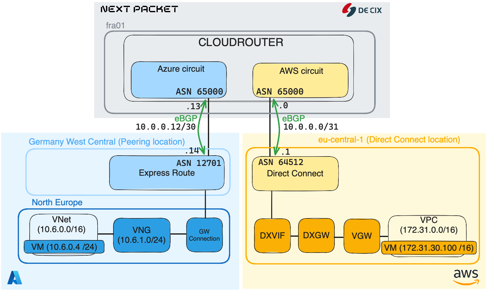
In our infrastructure we have 3 main ingredients, Cloud Router, AWS and Azure. The idea is to interconnect AWS and Azure via Cloud Router. It will be achieved by creating two circuits, one from Cloud Router to AWS, and another from Cloud Router to Azure.
After both AWS and Azure circuits are set up, each CSP will be configured to advertise their BGP prefixes to the Cloud Router, which will then incorporate them into a dedicated routing table within a VRF.
By doing so, Cloud Router will act as a glue and allows both AWS and Azure infrastructure to communicate thanks to a dedicated connection.
Components
Below the detail of each components that we are going to play with:
Cloud Router
Cloud Router is a router installed in a datacenter where you can have a dedicated VRF and interfaces. In our case, it will be used to interconnect both AWS and Azure network.
Azure
In the cloud’s Microsoft we will use three services: Express Route, Gateway Connection and Virtual Network Gateway. Below are further details for each of them.
- Express route: This is the Azure product to do a dedicated connection. Like AWS Direct Connect, Azure ExpressRoute circuits can be established with different bandwidth options, but there is a major difference with Express Route because it is deployed with a built-in redundancy, meaning you have two handover points possible (two peering sessions).
- Gateway connection: In the context of Azure, the Gateway Connection typically refers to the connection between an on-premises network and an Azure Virtual Network. It will help us to establish the connection between the Express Route circuit and the Virtual Network Gateway.
- VNG (Virtual Network Gateway): The gateway that allows your VNet (similar to AWS VPC) to reach another VNet. It acts as the anchor point for multiple types of Azure network functionalities like VPN, ExpressRoute, and more.
- VNet (Virtual Network): It is a network or environment that can be utilized to run virtual machines and other services in Azure.
AWS
In AWS, it is four services that we will use in this setup: Direct Connect Connexion, Direct Connect Virtual Interface, Direct Connect Gateway, Virtual Provate Gateway:
- DXCON (Direct Connect Connexion): This is the dedicated connection product by AWS. As opposed to Azure Express Route, there is no built-in redundancy, that means you have to create two circuits if you want redundancy.
- DXVIF (Direct Connect Virtual Interface): A Direct Connect Virtual Interface allows you to configure L3 information and establish peering connection through your DXCON (Direct Connect Connexion).
- DXGW (Direct Connect Gateway): The Direct Connect Gateway is a global resource in AWS that allows you to connect multiple VPCs in different regions.
- VGW (Virtual Private Gateway): In AWS, there are two types of gateways: public (Internet Gateway, IGW) and private (Virtual Private Gateway, VGW). An Internet Gateway (IGW) is automatically attached to your VPC and serves as a router to access public resources outside of your VPC. By default, the IGW allows traffic with destination addresses specified by 0.0.0.0/0 or ::/0 to use the Internet Gateway. In our scenario, we will use a Virtual Private Gateway (VGW) because our requirement is to establish secure, private communication between the VPC and on-premises environments, rather than routing traffic to the public Internet.
- VPC (Virtual Private Cloud): A virtual environment, similar to Azure Vnet, enabling users to run AWS resources like VM in a logically isolated section.
To consider before deploying
Order implementation
It is possible to build such infrastrcture by starting from the top (top-down approach) or from the down (bottom-up approach).
Many organizations chose a top-down approcach and start with the network architecture, connectivity (such as ExpressRoute or AWS Direct Connect), and security policies. Once the backbone is in place, virtual network (Vnet, VPC, …), gateways, and resources (like VMs) as needed.
This article focus on a top-down approach. First, by configuring the Cloud Router circuits with Azure and AWS, then for each CSP their components until the VM.
Regional Scope
When establishing interconnections between cloud providers it is crucial to take into account the location of the connection product. Azure and AWS both provide the flexibility to set up connections regardless of the region where your cloud resources reside.
However, this flexibility can significantly impact your budget, especially if you interconnect regions that are geographically distant from each other.
As a best practice, it’s often beneficial to choose a connection product location that is geographically close to the cloud region where your assets are hosted.
Azure refers to this as the Peering location, while AWS uses the term Direct Connect location.
For example, in this article, the Azure peering location is Germany West Central and the closest region to it, to host VM and resources within Azure is North Europe. For AWS, the peering location is eu-central-1, and the same region is available to host VPC and AWS resources.
Optimizing the proximity of service locations ensures that your connections are highly efficient and low-latency, enhancing the overall performance and reliability, and also reducing costs.
PART I - Configuring Cloud Router, AWS and Azure circuits
That part will focus on ordering a Cloud Router instance, creating both AWS and Azure circuit, and on top of it configuring a BGP relationship. At the end of this part we should have:
- a Cloud Router instance up and running
- two BGP peering, one with AWS and one with Azure
Below, the components that we will setup in PART I:
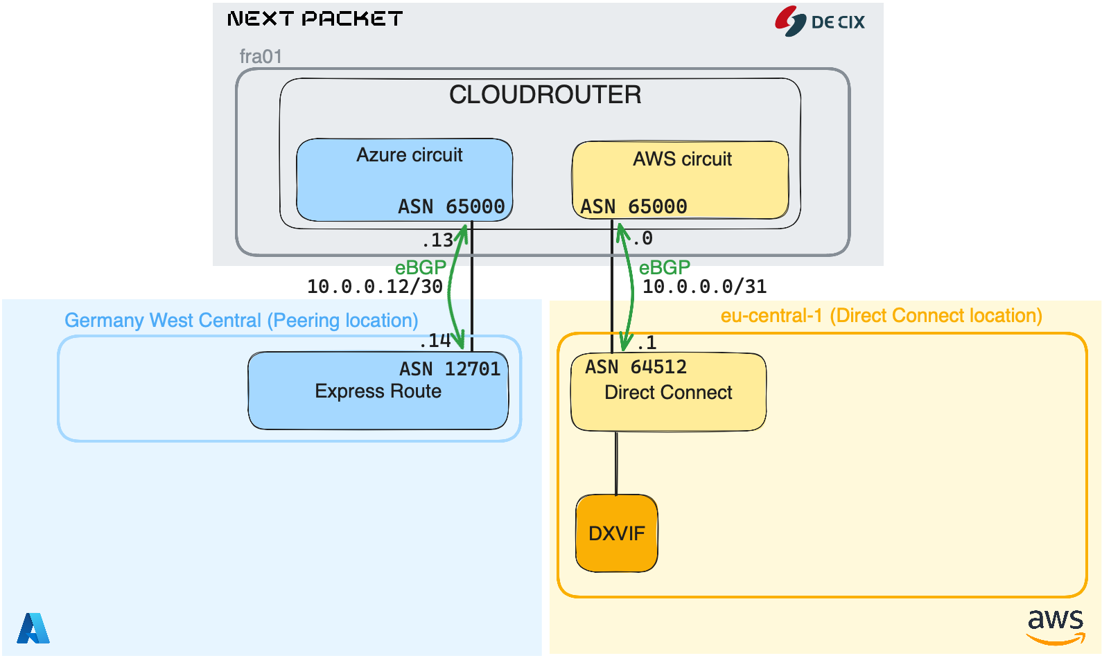
Cloud Router
Cloud Router is a product created by Next Packet in association with DE-CIX (Deutsche Commercial Internet Exchange). Like Equinix Edge or Packet Fabric, it allows you to have a routing instance in the cloud to expand your backbone. In comparison with other providers, Next Packet Cloud Router allows you to have either a virtual or a bare metal router1 located on a DC. You can have a Cloud Router instance at every location where DE-CIX offer an on-ramp path. You can use it as a glue to interconnect your on-prem DC to your public cloud infrastructure, or to interconnect several cloud provider together.
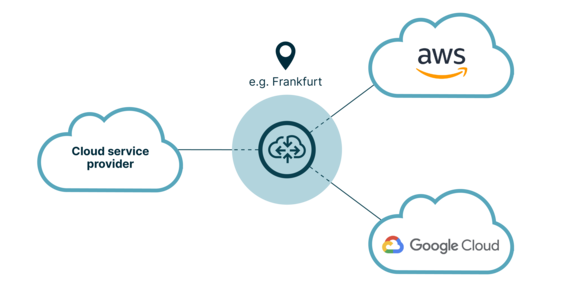 DE-CIX Cloud Router use-case example
More info about Cloud Router : https://www.de-cix.net/en/about-de-cix/news/de-cix-cloudrouter-interconnection-made-easy
We are going to configure two peering sessions inside a VRF, one for AWS and one for Azure. The idea is to advertise prefixes to your Cloud Router from both AWS and AZURE side.
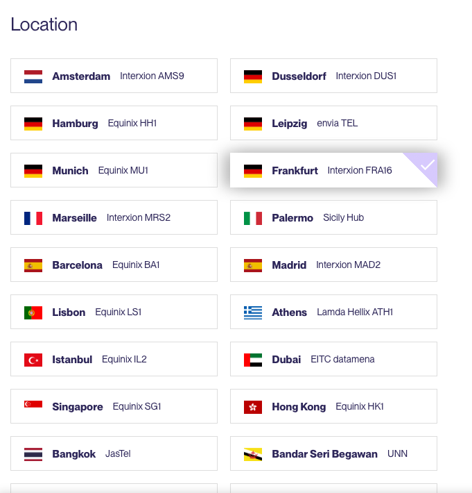
The Cloud Router instance we’re testing today is located in Frankfurt. Location is an important factor to consider, as it enables to effectively reduce costs and latency when interconnecting with a CSP.
Let’s have a look inside a Cloud Router instance:
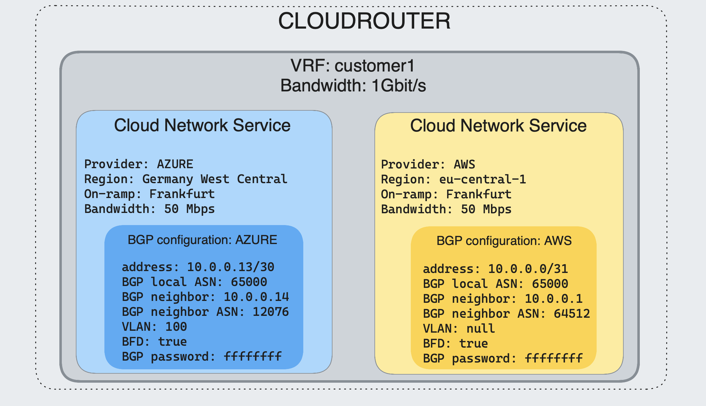
A Cloud Router instance is a logical slice of a Juniper device. The isolation is made thanks to a Juniper’s feature called logical systems. It offers routing and management separation. Management separation means multiple user access. Each logical system has its own routing tables. More info about Juniper logical systems : https://www.juniper.net/documentation/us/en/software/junos/logical-systems/topics/topic-map/security-logical-systems-for-routers-and-switches.html
Request a Cloud Router instance
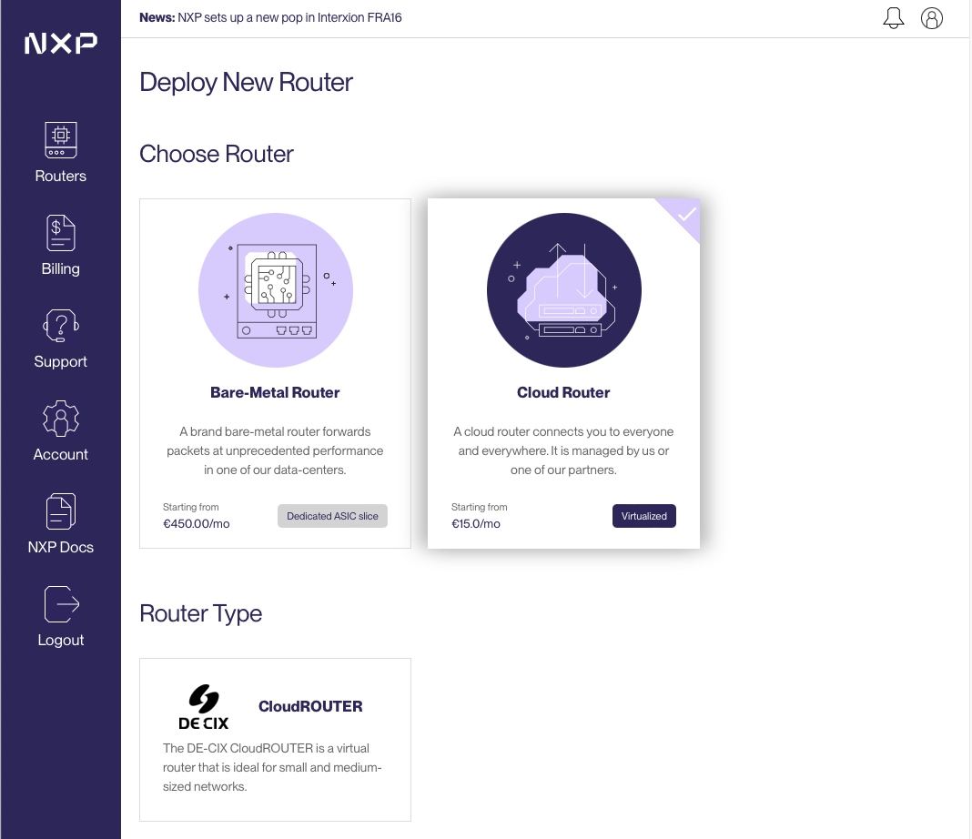
Go to the Next Packet website app.nextpacket.net, select Cloud Router, chose a location and a router hostname. As Cloud Router is developed and maintained by DEC-IX, you can benefit from its broad presence in data centers, providing access to numerous locations.
Configuration
There are three ways to configure Cloud Router :
- Next Packet frontend
- APIs (Postman, curl, …)
- Infrastructure as Code (IAC). Thanks to the IX-API, an IAC way will be available soon and you will be able to deploy a CR instance with Terraform
More info about IX-API: ix-api.net
Terraform registry: https://registry.terraform.io/providers/ix-api-net/ixapi/latest
Postman is the way that we will configure Cloud Router. First you need to get the postman environment (provided by the Next Packet Team), you can ask a demo here: Next Packet Demo
As soon as you get the Postman collection, follow these instructions to load the environment into Postman: 1. Import both the environment and the collection into your local postman installation
2. Select the environment called “nextPacket”
3. Click on the collection folder and open the Tab “Authorization”, scroll all the way down to “Get New Access Token”, click the button
4. Login or create a user
5. Once Authenticated click on proceed and then “Use Token”
6. The token may expire after 5 minutes. The newest postman version is able to auto-refresh the token for you. Please double-check for a message like “Expires at xx pm today. Refresh”. If you can see that, you can be certain the feature works
The environment allows to interract with our Next Packet account, in our case it is mainly a set of 3 API calls that we are hoing to use:
- A call for provisioning Cloud Router (ProvisionCloudRouter)
- A call for provisioning an AWS circuit (ProvisionAwsCircuit)
- A call for provisioning an Azure circuit (ProvisionAzureCircuit)
Provisioning CloudRouter
Before requesting a Cloud Router instance, we should know in which datacenter we want to install Cloud Router. It should be the closest to our Azure Peering Location and AWS Direct Connect Location. To obtain the list of DC on which Cloud Router is available, go into Postman > folder NextPacket > select the Catalog POST method.
In my case, both Azure Peering and Direct Connect location are in Franfurt (Germany).
💡 If you get a 401 Unauthorized, remember to get a new access token (in the 6th bullet point in the previous paragraph).
When you click send, in the response body you should have the list of every location where you can have a Cloud Router instance. Below the one we are interested today:
{
                "id": "00000000-6f43-4a46-8e64-b742256c1825",
                "name": "Interxion FRA16",
                "metroArea": "Frankfurt",
                "countryCode": "DE",
                "longitude": 8.734662,
                "latitude": 50.119794,
                "url": "https://www.interxion.com/locations/europe/frankfurt/fra15"
            }
Copy the datacenter id (value of the id key, here 00000000-6f43-4a46-8e64-b742256c1825) and in Postman go to NextPacket > CloudRouter > ProvisionCloudRouter.
In the Body tab, Query section
mutation ProvisionCloudRouter(
        $routerName: String!,
        $dataCenterId: ID!,
        $asn: Int!,
        $capacity: Int = 1000) {
    provisionCloudRouter(routerName: $routerName,
        dataCenterId: $dataCenterId,
        asn: $asn,
        capacity: $capacity)
}
Here I set $capacity: Int = 1000, that means the CloudRouter will be configured with 1Gbps has backplane capacity, meaning up to 1Gbps of circuit can be managed.
GraphQL variables section In dataCenterId put the DC id previsouly copied (about Frankfurt DC).
{
    "routerName": "{{$randomBs}}",
    "dataCenterId": "00000000-6f43-4a46-8e64-b742256c1825",
    "asn": 65000
}
Then click on Send button and it should be able to create the Cloud Router instance with the specified parameters.
Once it is provisioned, you should have a 200 OK status and get a Cloud Router provision ID.

Let’s have a closer look to the Cloud Router instance. By connecting onto it with ssh or via the Next Packet portal you can get a web ssh-based access to run CLI commands. As you can see, it is a routing instance inside an MX204 Juniper router. The isolation is made thanks to logical systems, which creates a VRF and isolate it from other tenants.
jvetter@nxp-fra-01:l2> show version
Hostname: nxp-fra-01
Model: mx204
Junos: 21.3R3-S4.2
JUNOS OS Kernel 64-bit  [20230228.eb13e1d_builder_stable_12_213]
JUNOS OS libs [20230228.eb13e1d_builder_stable_12_213]
JUNOS OS runtime [20230228.eb13e1d_builder_stable_12_213]
JUNOS OS time zone information [20230228.eb13e1d_builder_stable_12_213]
JUNOS network stack and utilities [20230331.040304_builder_junos_213_r3_s4]
JUNOS libs [20230331.040304_builder_junos_213_r3_s4]
JUNOS OS libs compat32 [20230228.eb13e1d_builder_stable_12_213]
JUNOS OS 32-bit compatibility [20230228.eb13e1d_builder_stable_12_213]
AWS
Configuring the circuit and the BGP relationship
Now the Cloud Router instance is up and running, we need to setup the AWS circuit and attach to it. First, let’s get our AWS account ID, which is a unique 12-digit number that identifies your AWS account. You can find your AWS account ID in the AWS Management Console by navigating to the Support Center and clicking on the “Support Center” menu item. Your account number will be displayed in the upper-right corner of the Support Center page.
Alternatively, you can use the following AWS CLI command to retrieve your account number:
$ curl "https://awscli.amazonaws.com/AWSCLIV2.pkg" -o "AWSCLIV2.pkg"
$ aws sts get-caller-identity
$ aws sts get-caller-identity --query 'Account' --output text
Then, in Postman go to Cloud Router folder and click on ProvisionAwsCircuit.
In the body tab, GraphQL variables section
{
    "cloudRouterId": "{{cloudRouterId}}",
    "accountNumber": "112233446655",
    "bandwidth": 50,
    "dataCenterId": "00000000-6f43-4a46-8e64-b742256c1825",
    "localIpAddress": "10.0.0.0",
    "remoteIpAddress": "10.0.0.1",
    "prefixLength": 31,
    "localAsNumber": 65000,
    "remoteAsNumber": 64512,
    "md5Key": "abcdefgh"
}
Below the detail of each key:
accountNumber: Your AWS account numberbandwidth: The bandwidth of the circuit (in Mbps)dataCenterId: This is the place where you connect to the AWS Direct Connect Location. Here select the same id from the catalog, as you specified for the Cloud Router ProvisioninglocalIpAddressandremoteIpAddress: The IP address for the BGP peering between Cloud Router (local) and AWS Direct Connect (remote)prefixLength: Here we put 31 (meaning /31 subnet mask)localAsNumberandremoteAsNumber: Local and remote AS Number for the BGP peeringmd5key: Protection of BGP Sessions via the TCP MD5 Signature Option (RFC 2385)
Once the query is complete, click on the Send button.
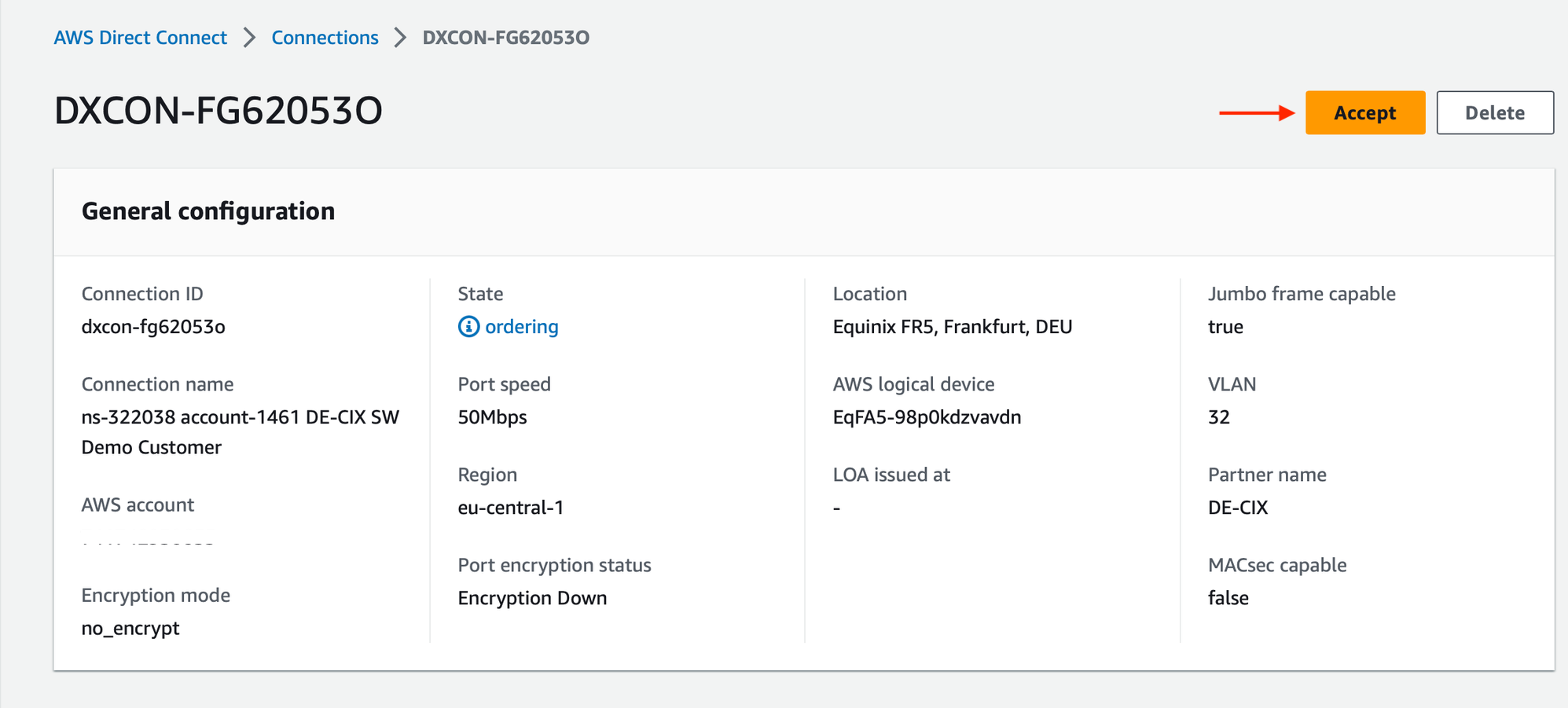
After submitting the Postman request, you should see the Direct Connect order creation on your AWS dashboard. Go on the AWS > Direct Connect page > Connections, here you will see the Direct Connect Connection in ordering state (it can take between 60 and 120 sec).

Click on it and select Accept:
Configuring a Direct Connect gateway (DXGW) with a Direct Connect interface (DXVIF)
Now we will create a Direct Connect Gateway (DXGW) and attach a virtual interface to it. The Direct Connect gateway is as its name implies, a gateway, and it acts as a central hub to allow multiple VPC in different region to use a Direct Connect connection. The virtual interface will be configured with the BGP peering information and allows us to establish a peering relationship with the Cloud Router instance.
First, let’s create the Direct Connect gateway. To do so, in AWS go to the Direct Connect page > Direct Connect gateways > Create:
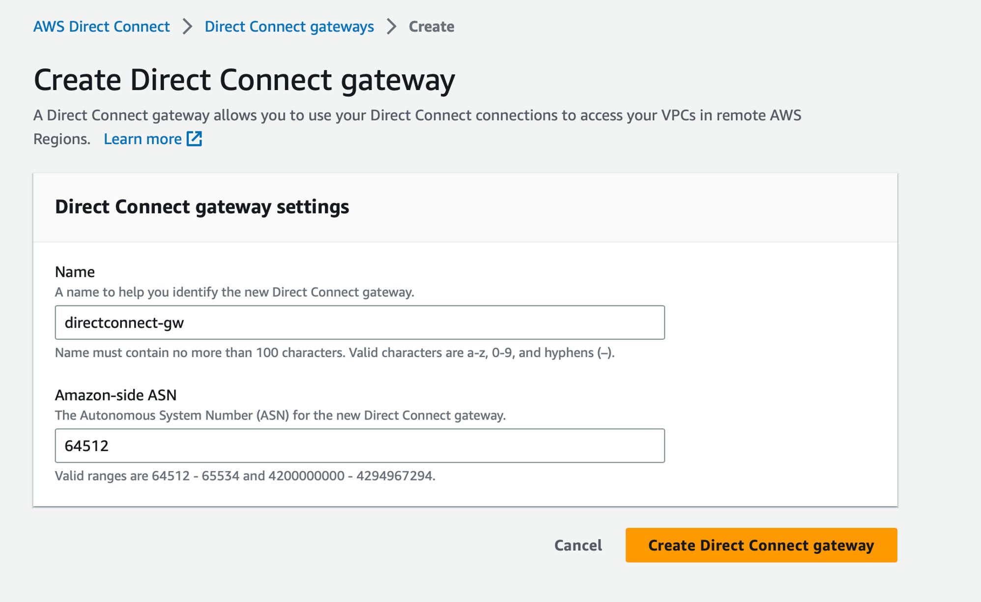 Specify a name for the Direct Connect gateway, and for the Amazon-side ASN field, use the one specified in the Postman Query as
 remoteAsNumber (in our case 64512). Then clic on the Create Direct Connect gateway button.
It is now visible in the Direct Connect gateways page:

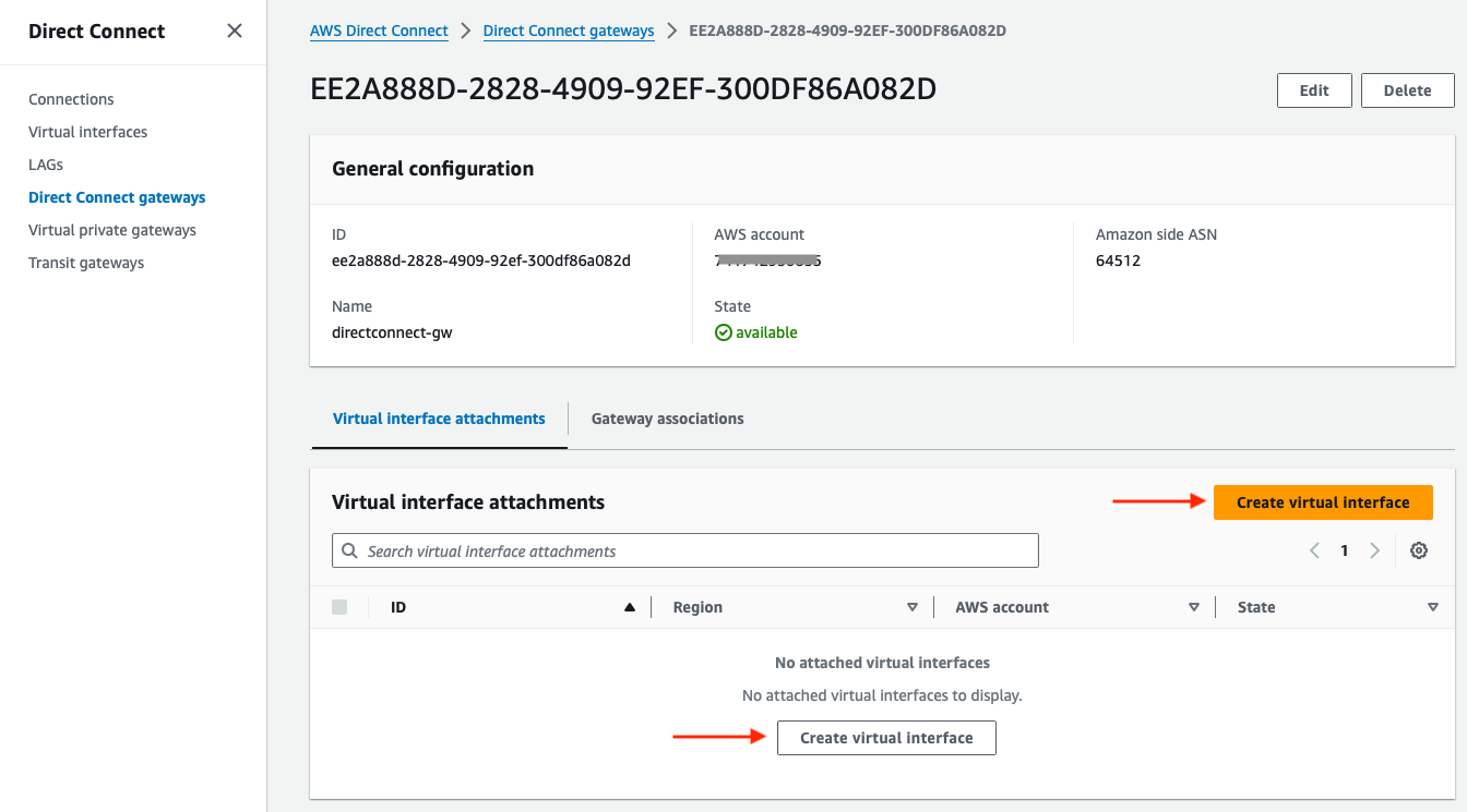
Below the Direct Connect gateway page there is the Virtual interfaces option. Click on Virtual interface attachments, then click on Create virtual interface (either via the orange button on the right, or the button below “No attached virtual interfaces”):
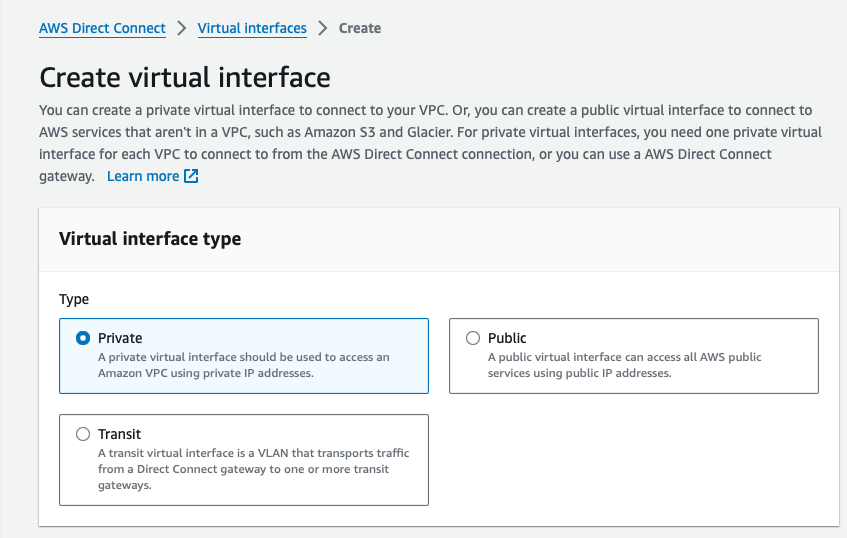
Virtual interface type
First, select Private as Virtual interface type:
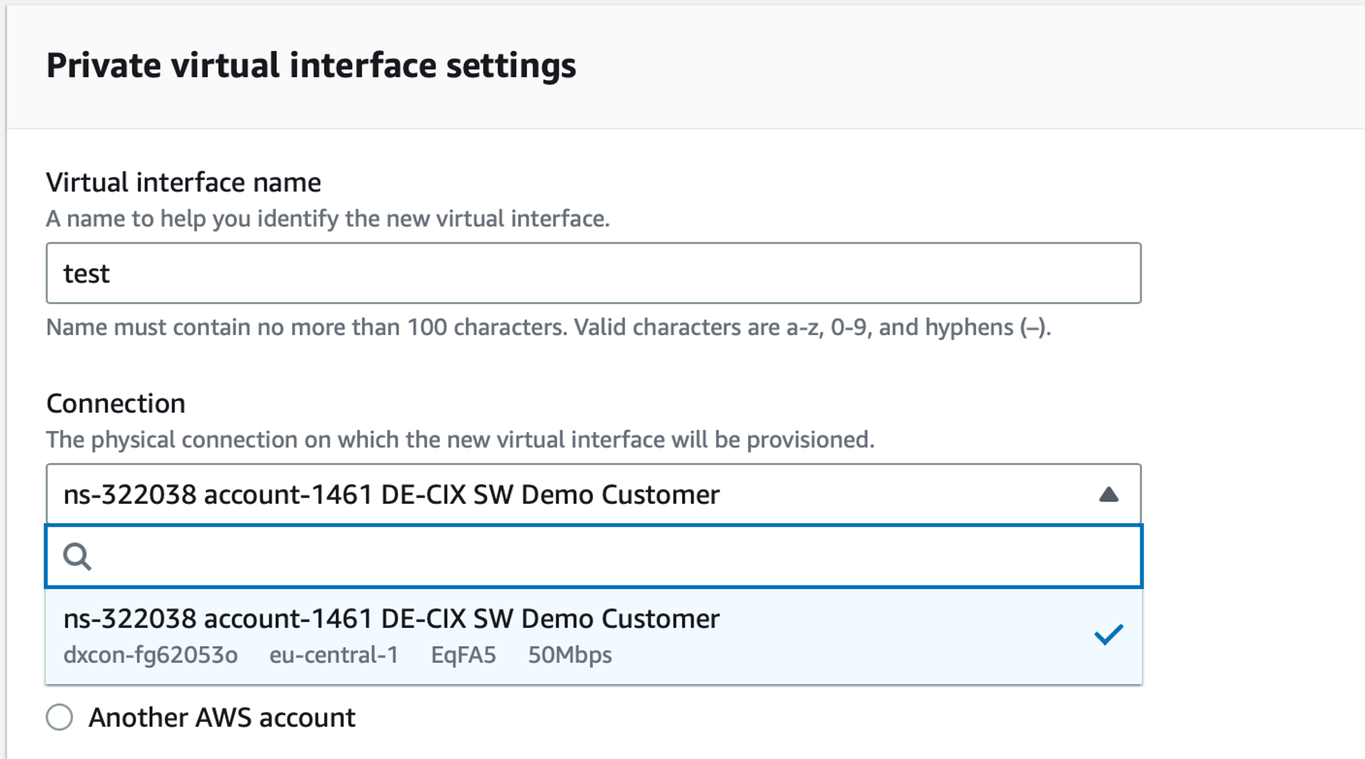
Private virtual interface settings
Below, in the Private virtual interface settings, give a name to the Virtual interface and select the circuit you previously made (at 50Mb/s):
Then specify the configuration for the Virtual interface owner, Gateway type and Direct Connect gateway:
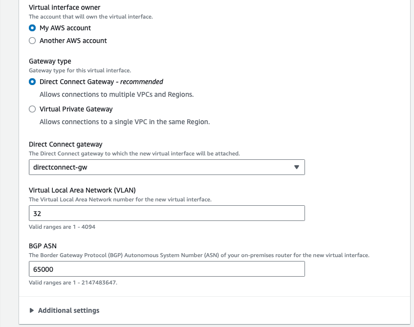
Virtual interface owner section:
- Select “My AWS account”
Gateway type section:
- Select Direct Connect Gateway
- In the drop-down field select the Direct Connect gateway just previously created
- Chose a VLAN number between 1 and 4094 (which is an inner-VLAN, or C-VLAN) for that particular Virtual interface
- BGP ASN is the neighbor BGP ASN. Specify here the one configured as local ASN for the Cloud Router instance (65000)
Below, in Additional settings, configure the BGP neighbor address and the TCP MD5 BGP peering authentication:
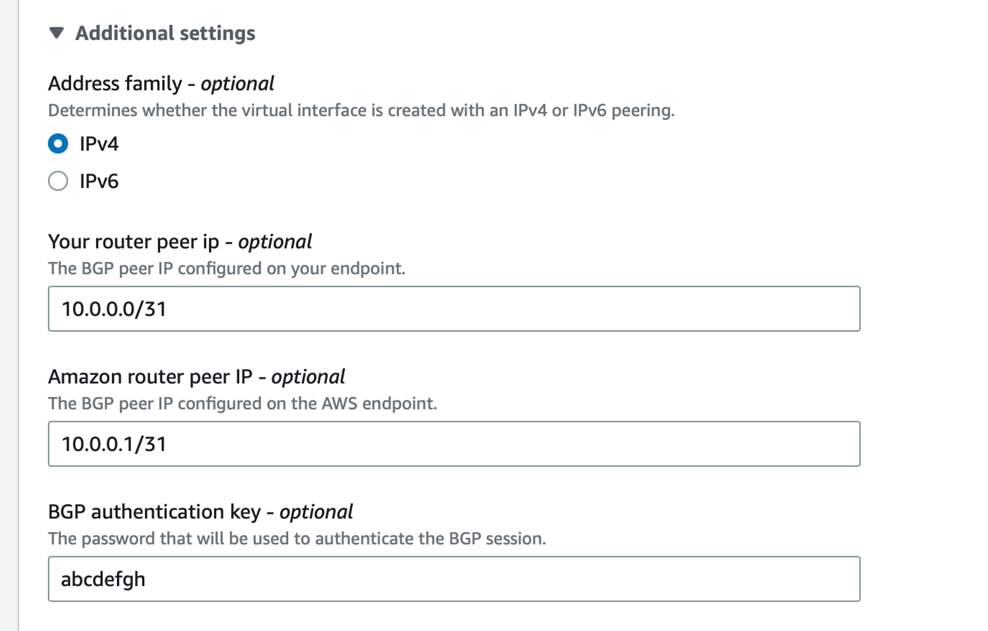
- Adress family: IPv4
- Your router peer IP: meaning the BGP neighbor IP, which is the IP configured on the Cloud Router for the AWS circuit (10.0.0.0/31)
- Amazon router peer IP: specify the AWS side IP address used for the BGP peering, which is the second IP of the 10.0.0.0/31 range, so 10.0.0.1
- BGP authentication key: same key as configured in Cloud Router via the
ProvisionAwsCircuitquery,md5Keykey value
💡 You cannot define the same L3 network if you have created another circuit on the same region.
Then click on Create virtual interface:
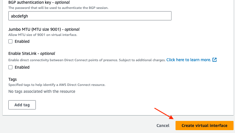
Once created you can see it under Virtual interfaces:

Checking AWS Direct Connect BGP status
Once the Direct Connect interface created, click on it to open its page. Below this page there are 4 tabs: Peerings, Monitoring, Tags and Test history. Select Peerings and you’ll see the BGP peering information with the reliationship status.

AZURE
Configuring the circuit and the BGP relationship
Similarly on what we achieved with AWS, we will now replicate the process on Azure.
The first step involves creating the circuit to establish the BGP peering connection, the Azure service to do that is called Express Route. Following that, we’ll generate a Virtual Network Gateway (comparable to AWS Virtual Private Gateway) and establish a Gateway Connection to bridge the Virtual Network Gateway with the Express Route circuit.
In the Azure portal, type ExpressRoute in the search bar to find the ExpressRoute circuits servce. It opens the ExpressRoute page, here click on Create:

On the page Create ExpressRoute: Project Details
- Subscription and Resource group: specify the one according to your account
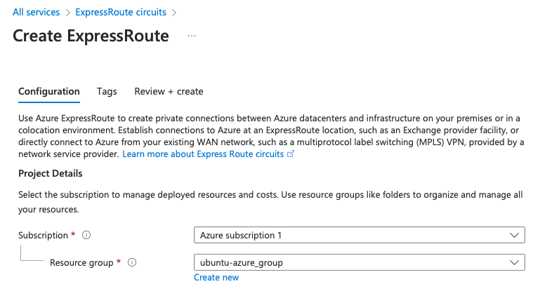
Circuit Details
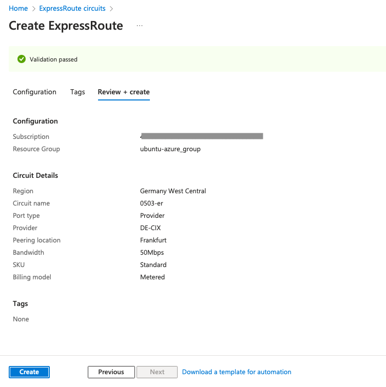
- Region: Germany West Central (located in Frankfurt, Germany West Central is the chosen region for our setup. Once more, we want to establish a circuit as close as possible to our Cloud Router)
- Circuit name: Specify a name for the ExpressRoute circuit
- Port type: Provider
- Provider: DEC-IX
- Peering Location: Frankfurt
- Bandwidth: 50Mps
- SKU2: Standard
- Biling model: Metered
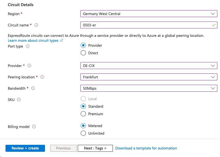
Then click on Review + create, and confirm the by clicking on Create:
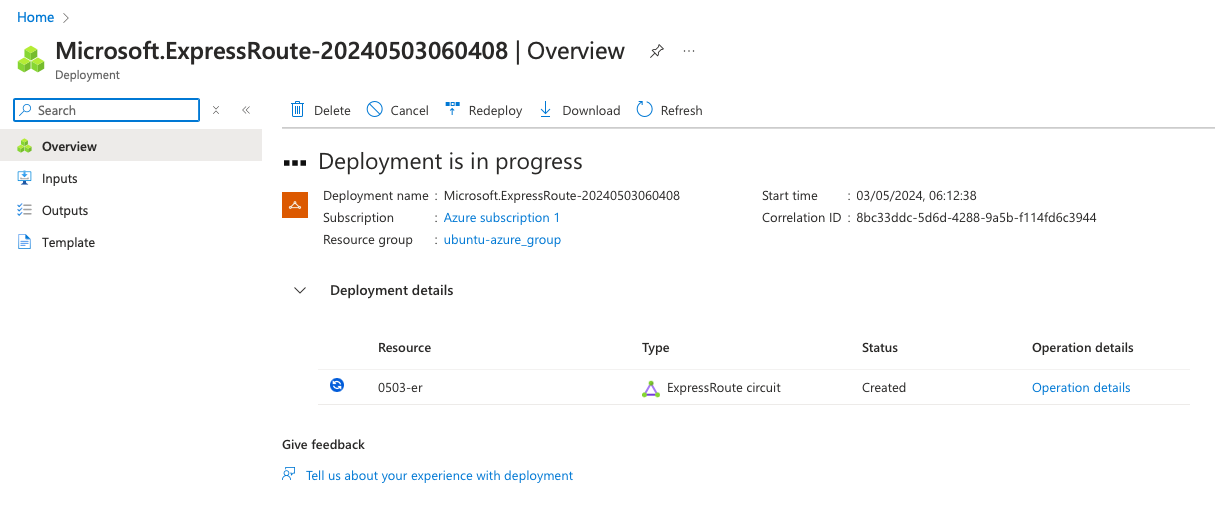
You should see Deployment is in progress:
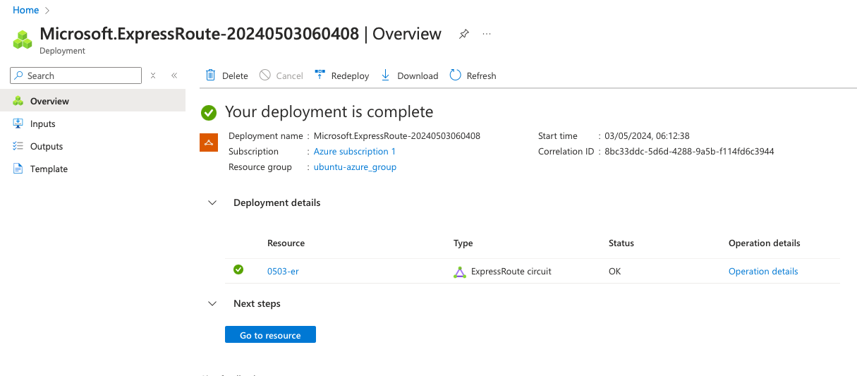
As soon as the deployment is complete, click on Go to resource to reach the ExpressRoute main page.
ExpressRoute Service key
In order to establish a circuit between Cloud Router and Azure ExpressRoute, you will need to inform your Cloud Router instance about the ExpressRoute circuit. This will be done by specifying the ExpressRoute service key in the appropriate Postman request.
On the ExpressRoute main page, you can see the Service Key. We will need it to provision the Cloud Router.

Cloud Router and Azure BGP configuration
Now let’s configure the BGP session between Cloud Router and Azure ExpressRoute. First, go back to Postman > Cloud Router > ProvisionAzureCircuit.
Configure the GraphQL variables as the follows:
{
    "cloudRouterId": "{{cloudRouterId}}",
    "serviceKey": "9433c213-a9a3-46d2-abc4-ef6dd5b9b353",
    "localIpAddress": "10.0.0.13",
    "remoteIpAddress": "10.0.0.14",
    "prefixLength": 30,
    "localAsNumber": 65000,
    "remoteAsNumber": 12076,
    "md5Key": "abcdefg",
    "innerVlan": 100
}
Here, set the serviceKey you found on the Azure ExpressRoute page. Also set all related IP BGP peering information, like local and a remote BGP neighbor address, the prefix lenght and local and remote IP neighbor.
Note:
- Azure doesn’t support /31 prefix lengths, so we use /30 here
- 12076 is the AS Number of Azure ExpressRoute
- Because Azure uses QinQ, an inner VLAN is set (C-VLAN or customer VLAN), let’s specify 100
Then click on Send, it will provision the Cloud Router with all information about the Azure circuit and the BGP settings.
Now go back on Azure, on the ExpressRoute page you should notice that the Provider status has transitioned from “Not Provisioned” to “Provisioned”.
Below on that page, there is the peering section, here click on Azure private 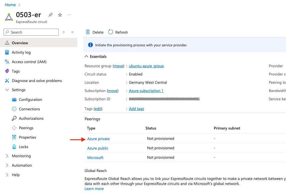
and configure as the following:
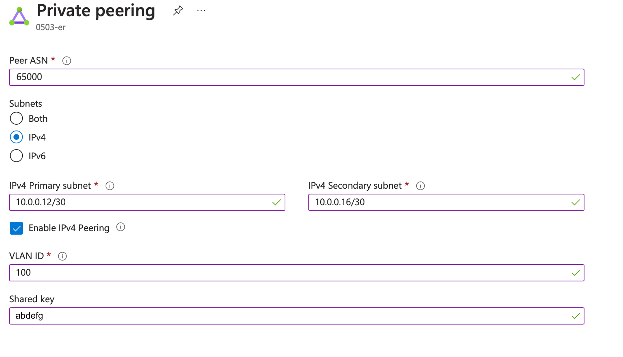
- Peer ASN: 65000
- Subnets: IPv4
- IPv4 Primary subnets: 10.0.0.12/30
- IPv4 Secondary subnets: 10.0.0.16/30
- Click on Enable IPv4 Peering
- VLAN ID: 100
- Shared key: abcdefg
Then click on Save at the bottom of this page.
💡 Note:
- Peer ASN: here set a public or private ASN. Note that you cannot use 65515 which is internally used by Microsoft
- In our setup, we designate only one handover path as primary, which means that the information provided in IPv4 Secondary subnets is not utilized but should still be specified. If you wish to utilize both primary and secondary circuits, you must configure this on the Cloud Router side as well
- You can use the two handover as active-active loadbalancing, then if you select 50Mbps link, you will have 100Mbps. You can also use those links as active/passive to have a fail-over connection
Checking Express Route BGP status
You can have information about the peering session by clicking on the three dots on the right hand side of the Azure private line.

The BGP status can be seen by clicking on the Route table summary:
 The state should turn to Establish after few seconds. In case it stays in Active or Idle state, we can connect to the Cloud Router instance to have a look.
Also, this page is very helpful to troubleshoot ExpressRoute connectivity.
Cloud Router BGP peering verification
Now we can connect to the Cloud Router instance to have a look to the BGP peering of both AWS and AZURE. From your Next Packet dashboard you can access to your Cloud Router instance via a web-based SSH interface.
Once connected to the Cloud Router, run the show interface terse command to check the interface status:
jvetter@nxp-fra-01:l2> show interfaces terse
Interface               Admin Link Proto    Local                 Remote
irb
irb.2                   up    up   inet     10.0.0.13/30
                                   multiservice
irb.4                   up    up   inet     10.0.0.0/31
                                   multiservice
Now let’s have a look to the BGP peers. Run the show bgp summary command:
jvetter@nxp-fra-01:l2> show bgp summary
Threading mode: BGP I/O
Default eBGP mode: advertise - accept, receive - accept
Groups: 2 Peers: 2 Down peers: 0
Peer                     AS      InPkt     OutPkt    OutQ   Flaps Last Up/Dwn State|#Active/Received/Accepted/Damped...
10.0.0.1              64512      11492      12391       0       2 3d 21:15:46 Establ
  d87ed303-8b9d-48a5-9f08-aa42b4b50cd8.inet.0: 1/1/1/0
10.0.0.14             12076     134743     136730       0       2 6w0d 21:26:31 Establ
  d87ed303-8b9d-48a5-9f08-aa42b4b50cd8.inet.0: 2/2/2/0
Both Azure and AWS BGP peering are established.
In case of troubleshooting, the ping command can be used from the Cloud Router instance to the remote peer (AWS and Azure). Because we are isolated inside a VRF, we have to specify the routing-instance when using the ping command.
Below an example by sending ICMP echo requests to check the Azure ExpressRoute connectivity:
jvetter@nxp-fra-01:l2> ping 10.0.0.14 routing-instance d87ed303-8b9d-48a5-9f08-aa42b4b50cd8
PING 10.0.0.14 (10.0.0.14): 56 data bytes
64 bytes from 10.0.0.14: icmp_seq=0 ttl=64 time=0.647 ms
64 bytes from 10.0.0.14: icmp_seq=1 ttl=64 time=0.599 ms
64 bytes from 10.0.0.14: icmp_seq=2 ttl=64 time=0.891 ms
^C
--- 10.0.0.14 ping statistics ---
3 packets transmitted, 3 packets received, 0% packet loss
Let’s summarise what we’ve done in the first part:
- Setup a Cloud Router instance
- Provisionned Cloud Router with both AWS and Azure circuits and configured a BGP peering session for each of those
- Verified the BGP sessions are established
In Part II and Part III, we will finish to setup the infrastructure for each CSP (AWS and Azure). Now that AWS and Azure has a functionning circuit and peering relationship with Cloud Router, we have to configure some services in order to allow each CSP resources using the circuit towards Cloud Router.
PART II - Finishing AWS side
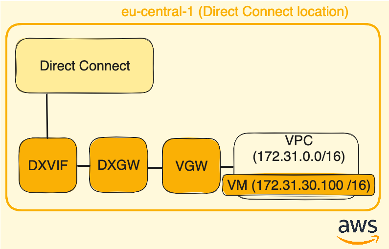
That part focus on configuring differents services in order to allow AWS resources (such as VM) to use the Direct Connect circuit. To do so, we will continue by adding a Virtual private gateway (VGW) and link it to the Direct Connect gateway (DXGW). Then we will ensure that the VPC is configured to use the Virtual private gateway.
Below, the resulting AWS infra at the end of that part:
Virtual private gateway (VGW)
We are almost done with the connection between AWS and Cloud Router. So far in AWS, we have created the Direct Connect connection circuit (DXCON), on which we attached a Direct Connect interface (DXVIF) and we linked that virtual interface to a Direct Connect gateway (DXGW).
Now we need to create a Virtual Private Gateway (VGW) to enable the VPC to communicate with our on-premise networks (Cloud Router in this case).
In AWS main page, on the top right side pay attention to be on the eu-central-1 region, then go to Direct Connect > select Virtual private gateways > click on the orange button Create virtual private gateway:

Give a name to your Virtual private gateway, select Cutom ASN and specify the AWS ASN side 64512:
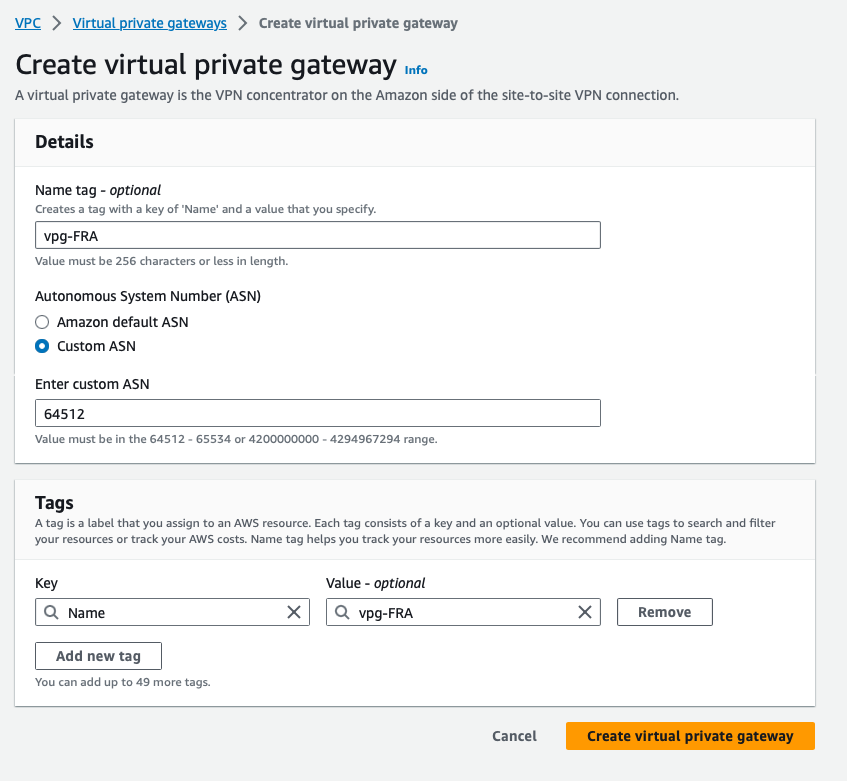
Once it is create, we need to be sure the Virtual private gateway is attached to our VPC. To verify, go to Direct Connect > Virtual private gateways > select the Virtual gateway newly created and click on the Edit button:
 Note that we have not created any AWS VPC in this tutorial, this is because we just use the default one created with your AWS account, which is a 172.31.0.0/16 subnet.
After clicking, it opens the Virtual private gateways page in the Virtual private network (VPN) menu. Select the Virtual private gateway > Actions, here Attached to VPC is greyed out if it’s already connected to your VPC. If it is not the case, just click on Attach to VPC and select your VPC.

Virtual private gateway (VGW) and Direct Connect gateway (DXGW) association
So now, we have a Virtual private gateway attached to our VPC, meaning any resources inside this VPC can use it as a gateway to reach Cloud Router and Azure resources.
But the chain is still incomplete, we need to associate the Virtual private gateway (VGW) with the Direct Connect gateway (DXGW):
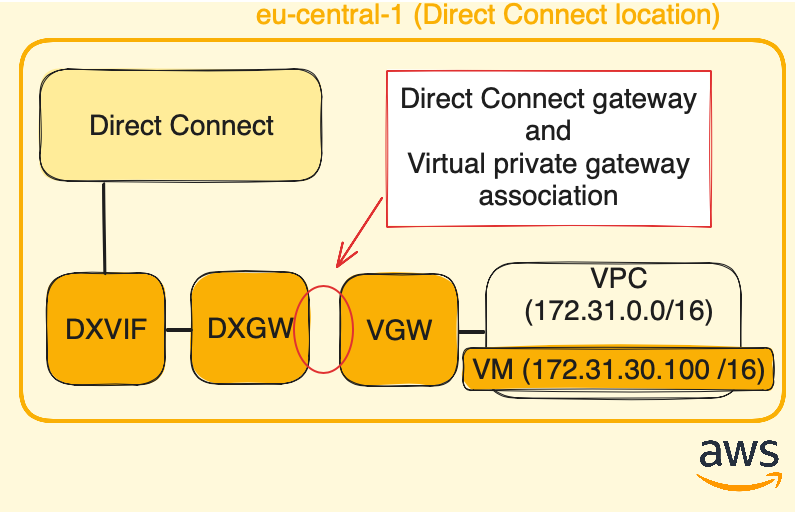
Go to the Virtual private gateways page, click on the Virtual private gateway ID to open its dedicated page:

Once open, below the General configuraiton details, there are two tabs: Virtual interfaces and Direct Connect gateway associations. Select Direct Connect gateway associations and click on Associate Direct Connect gateway.
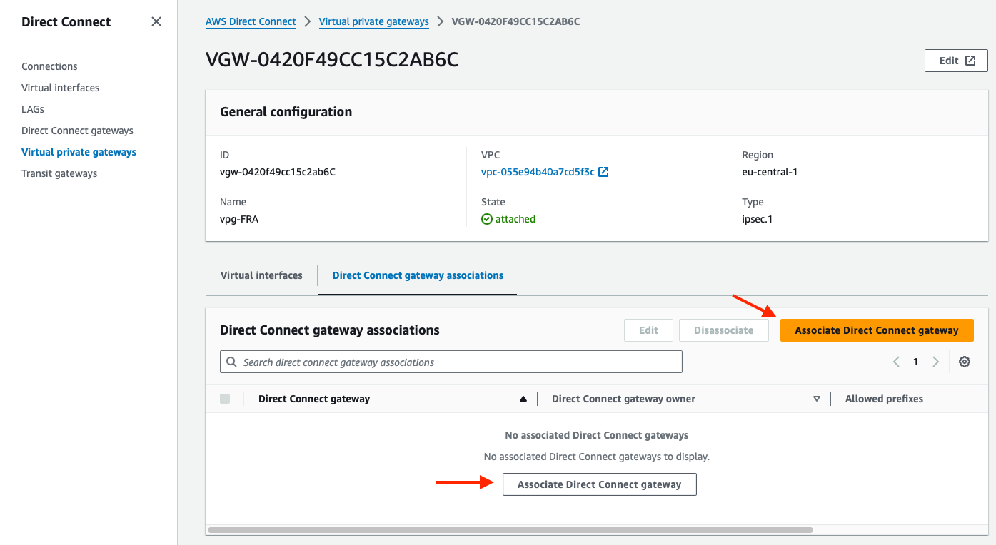
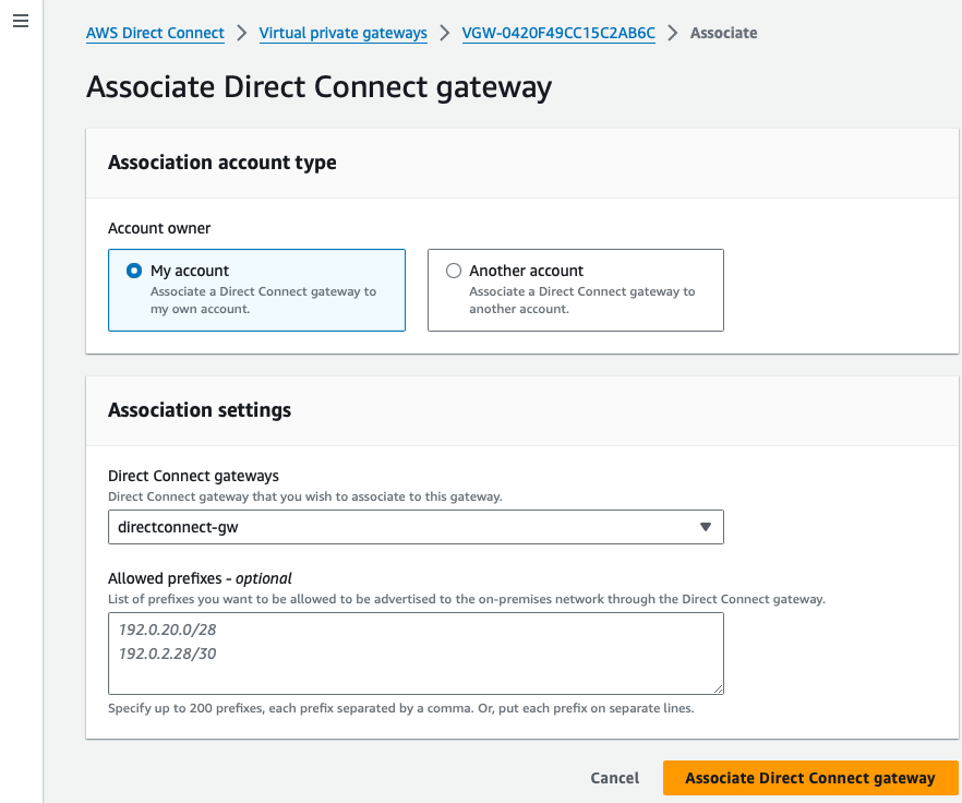
Select My account for the account owner.
In Association settings, Direct Connect gateways, use the dropdown menu to find the Direct Connect gateway previously created, and click on Associate Direct Connect gateway:
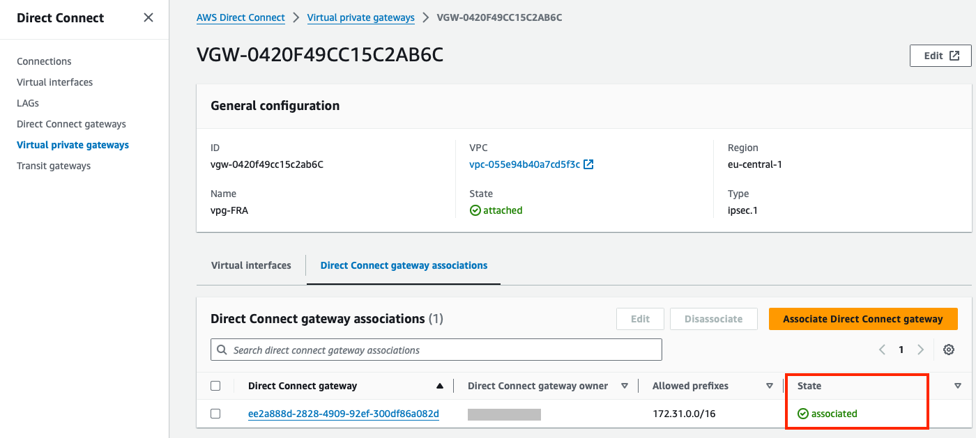
Now, below the Virtual private gateway page, Direct Connect gateways associations tab, we can see the Direct Connect gateway. The state can take a while to turn from *associating to associated:
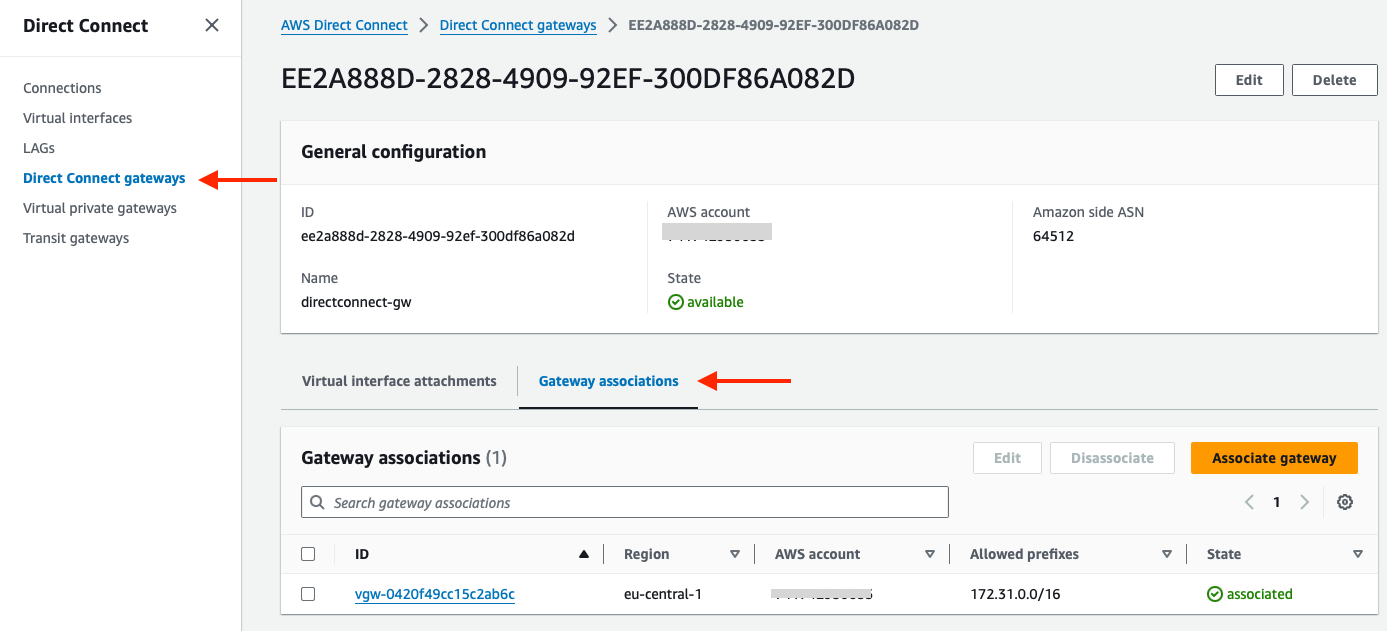
The gateway association can also be seen on the Direct Connect gateways page. Go to Direct Connect > Direct Connect gateways > select the Direct Connect Gateway and below you have the Gateway associations tab.
Was a Direct Connect gateway necessary?
The answer is no. It was not mandatory to utilize a Direct Connect Gateway to enable the AWS VPC to utilize the Direct Connect circuit. Neither selecting a Direct Connect Gateway association was required. A Virtual interface alone would have sufficed, as illustrated below:
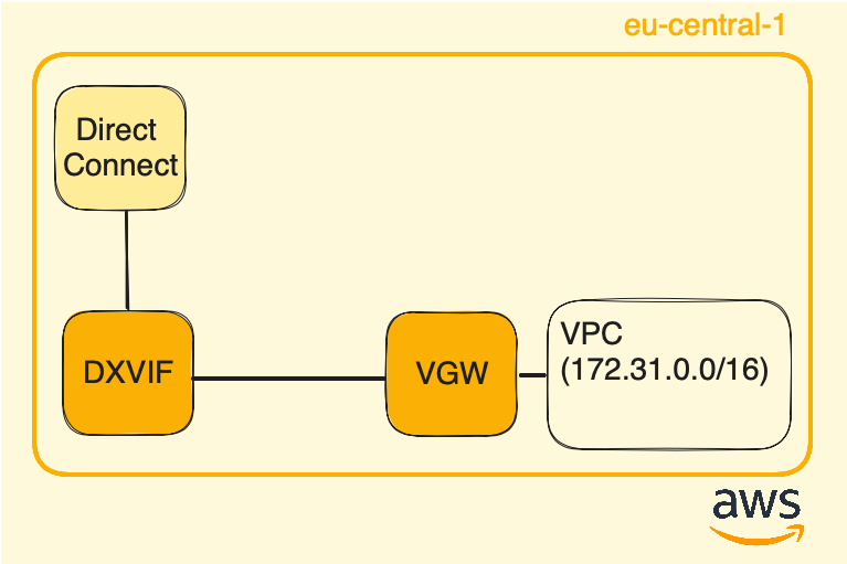
So, why opting for a Direct Connect gateway? Opting for a setup where the Direct Connect gateway is connected to a Virtual Private Gateway (VGW) allows for the expansion of the VPC’s private network into remote environments.
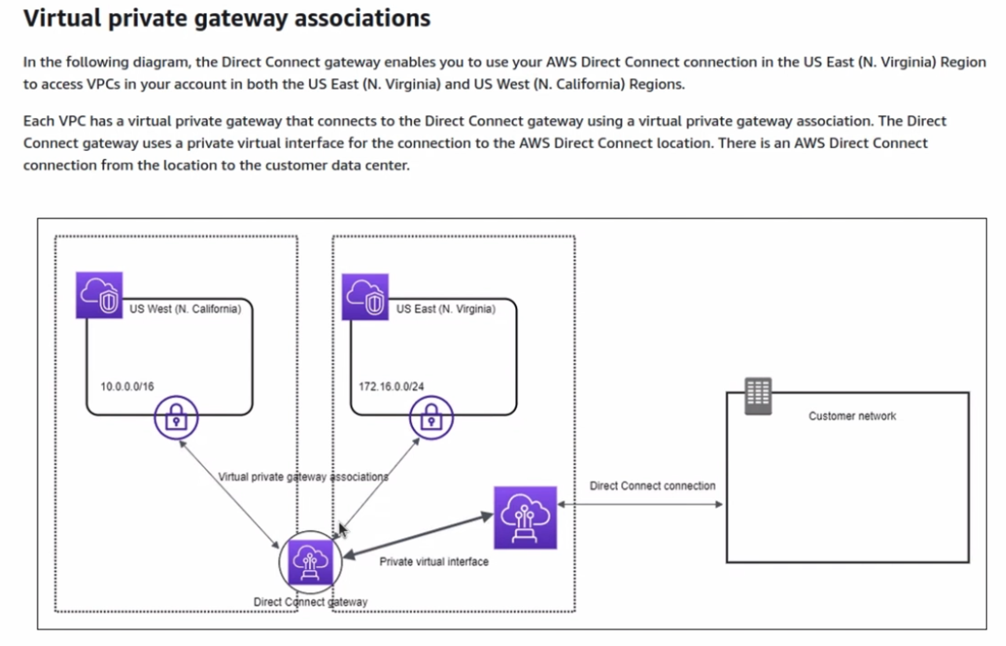
Unlike the Virtual private gateway, which is linked to a specific region (Frankfurt in our case), a Direct Connect gateway is region-independent. This allows you to extend your infrastructure by connecting it to another Virtual private gateway located on another region.
Below a diagram with two Virtual private gateways interconnected:
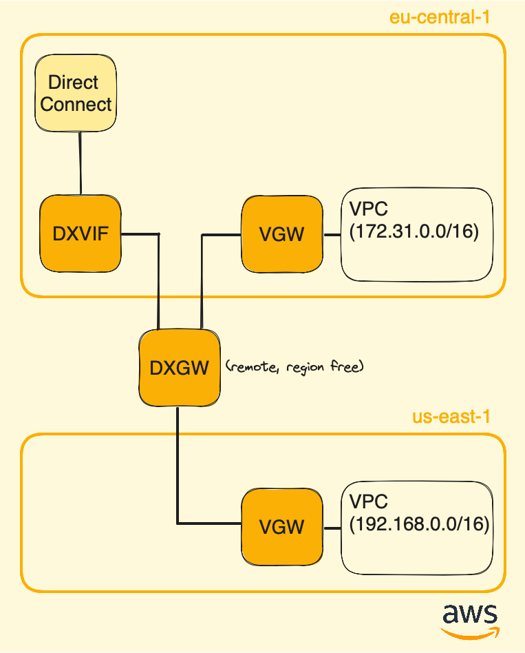
As mentionned before, using Direct Connect gateway allows to interconnect several Availability Zones (AZs), which locations are isolated within a cloud region designed to enhance availability and fault tolerance.
More information on the AWS website: https://docs.aws.amazon.com/directconnect/latest/UserGuide/direct-connect-gateways-intro.html
Enabling route propagation
In AWS, a Virtual Private Cloud (VPC) is automatically created for you by default. Each VPC is initially assigned a routing table that can only be updated manually. To automate the process of updating the routing table with prefixes learned via BGP, we need to enable the route propagation option.
Route propagation refers to the mechanism by which AWS automatically updates the VPC’s route table with learned routes (received via BGP) from the associated Virtual private gateway or Direct Connect gateway.
To do so, in AWS go to the search bar and type VPC, on the left side click on Your VPCs, then click on your VPC ID to open its page:

On the VPC Details page click on the Main route table (named rtb-xxx):
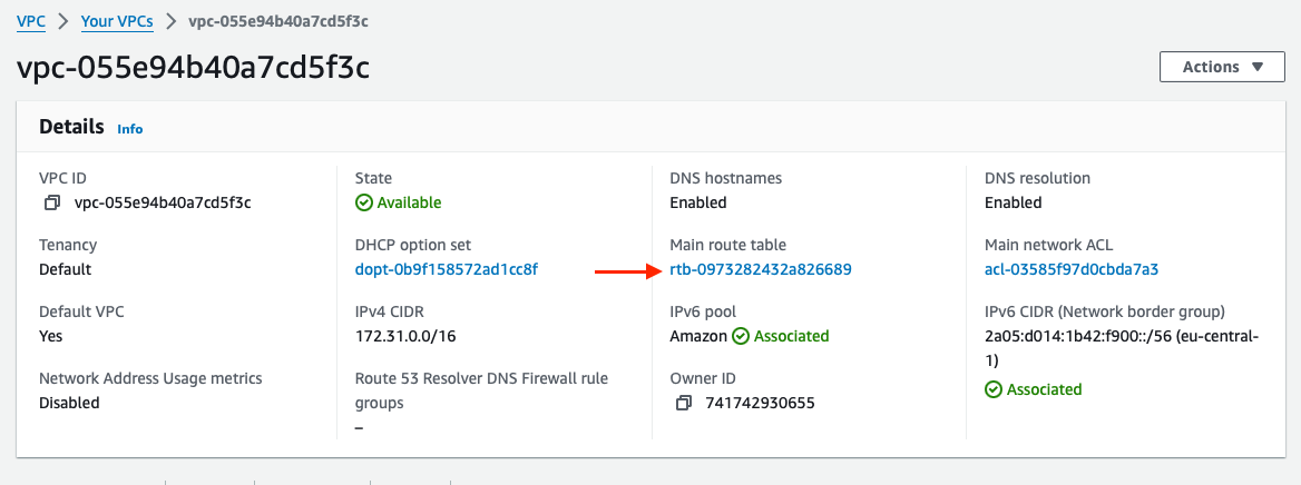
Once on the Route tables page, click on the Route table ID to open its page:

Below that page, go to the Route propagation tab and click on Edit route propagation:
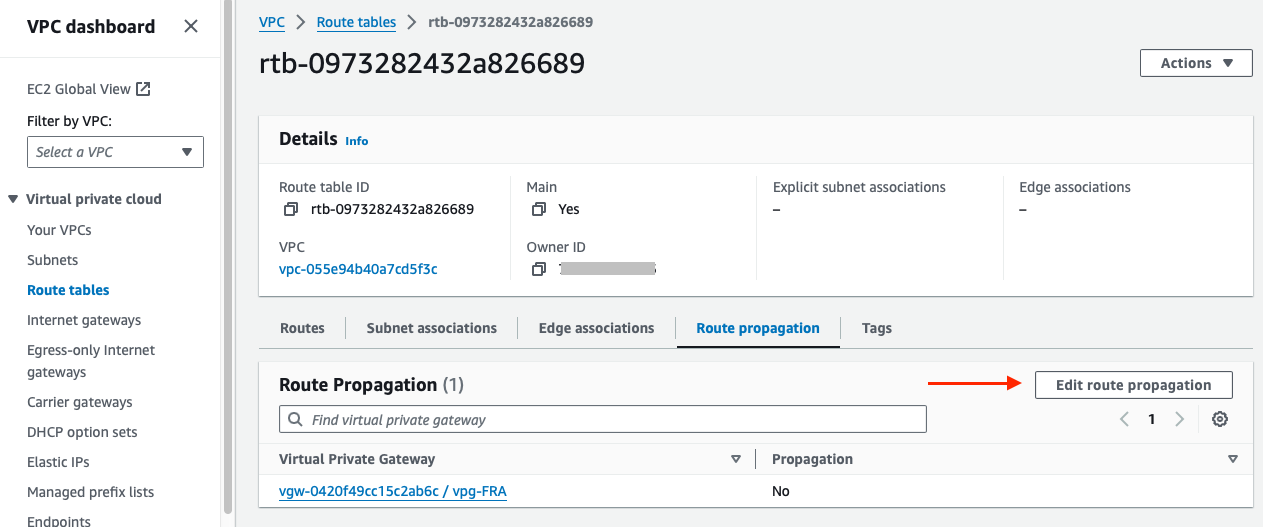
Now activate route propagation by selecting the checkbox labeled Enable, and click on Save:
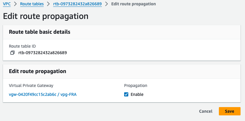
We are now done with the AWS infrastructure. Meaning that any resources using the VPC are able to use the Direct Connect circuit. Let’s proceed now with Azure.
PART III - Finishing Azure side
Similar to what we’ve done with AWS in Part II, here we need configure a connection between the ExpressRoute circuit and the Azure Virtual Network (VNet) in order to let machines and services running on Azure to use the ExpressRoute circuit. It is achieved by adding a Virtual network gateway (VNG), and it will be linked to the Express Route circuit with a service called Gateway Connection.
Below, the resulting Azure infra at the end of that part:
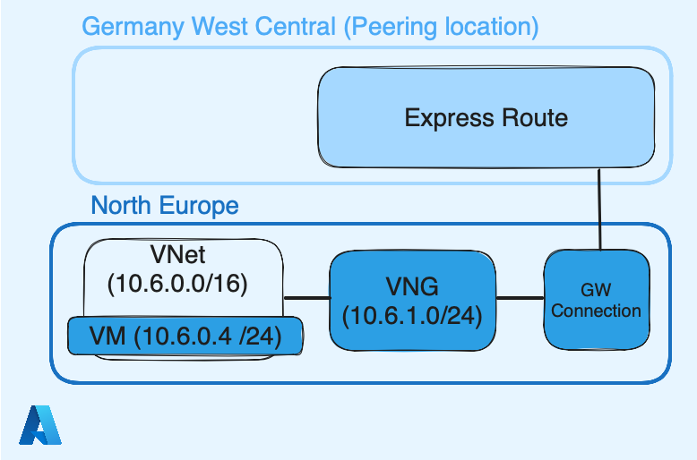
Azure VNet
Unlike AWS, which create a default VPC once you create your account, you should create and configure one with Azure and it is called VNet.
Connect to your Azure account, in the search bar look for Virtual networks:
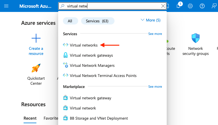
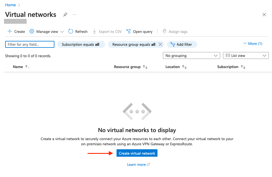
Then click on Create virtual network:
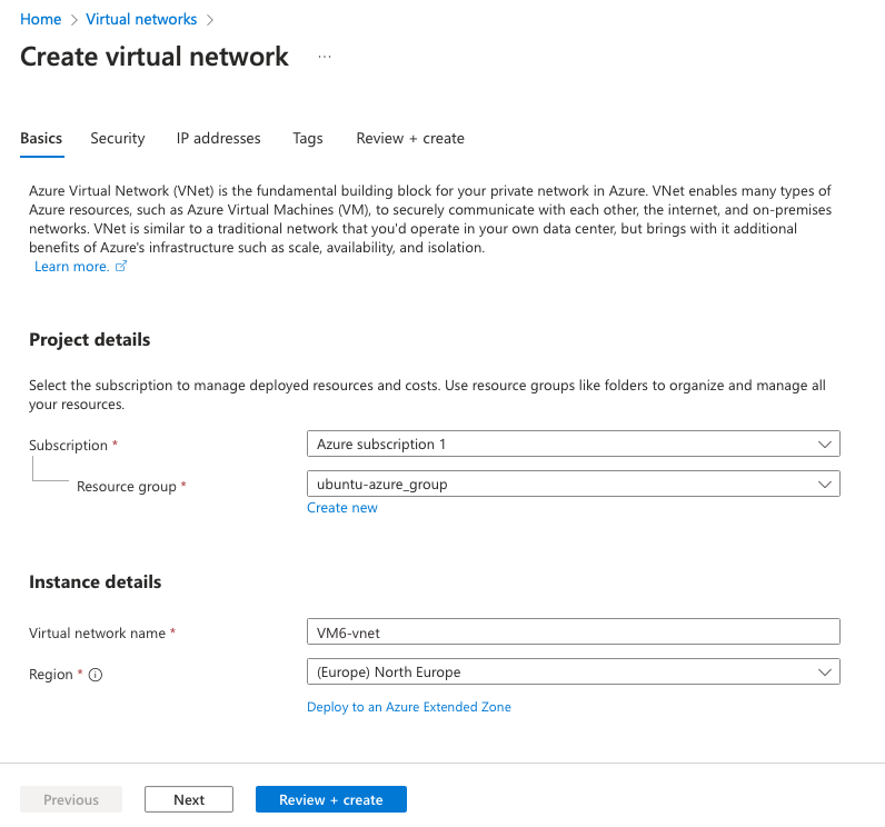
In Projet details select your appropriate subscription. In Instance details, give a name to your VNet and select North Europe as Region:
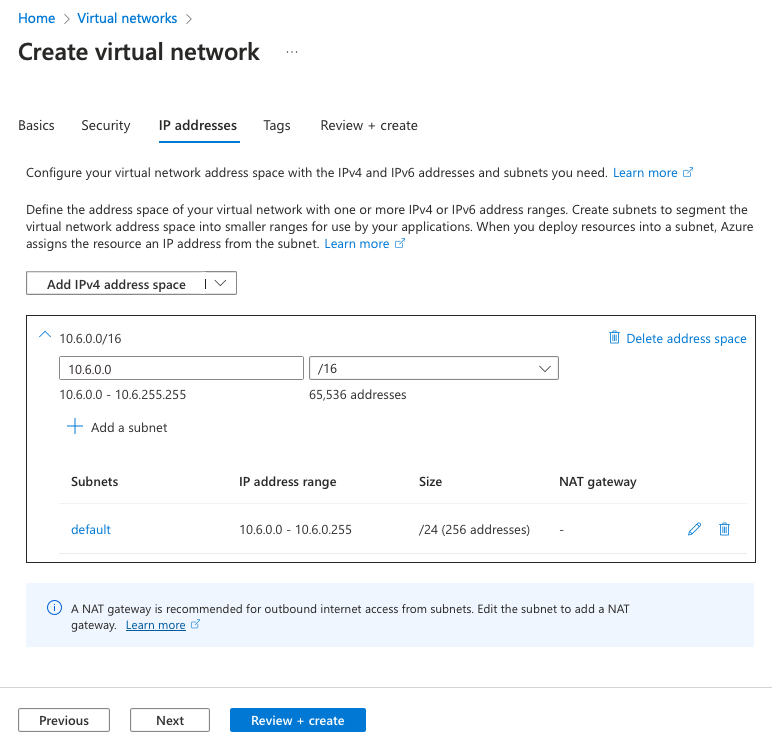
Go on the IP addresses tab in order to define your subnet. Here I define 10.6.0.0/16 as supernet, and 10.6.0.0/24 as default subnet (will be used by VM and resources inside this VNet), and finish by clicking on Review + create:
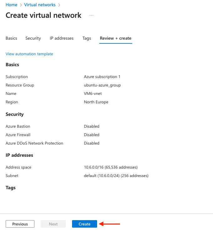
Review it and click on Create:
The next page should confirm the VNet deployment. Once deployed, click on Go to resource:
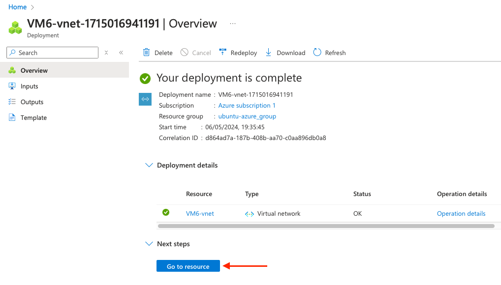
Now the VNet created, let’s define its gateway (VNG). The VNet resources will use it to reach AWS resources. Before creating the VNG, we should define a subnet range dedicated to it.
Once you are on the VNet page, go to Settings > Subnets and click on Gateway subnet:
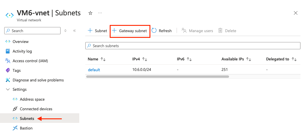
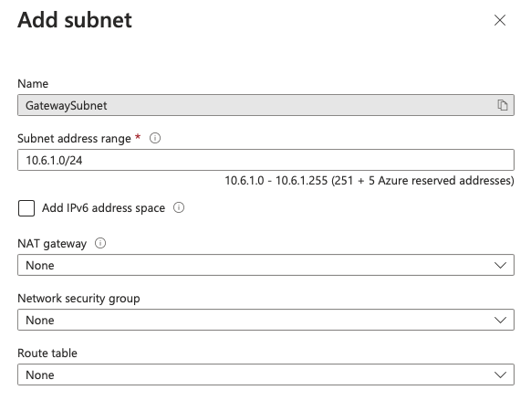
Here define a new /24, default subnet is 10.6.0.0/24, let’s pick 10.6.1.0/24. Let everything else by default and click on Save:
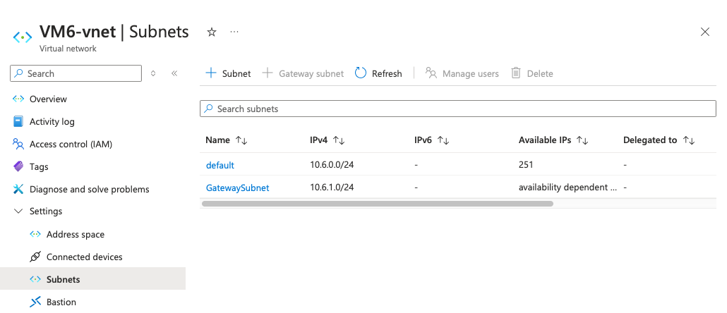
Two subnets should be present, default and GatewaySubnet:
Now we can continue with the Virtual Network gateway.
Azure Virtual network gateway (VNG)
As the name let implies, a Virtual Network Gateway (VNG) acts like a router and allows resources inside a Virtual Network (VNet) to reach other networks. We will then link that Virtual Network Gateway with the ExpressRoute circuit by using a Gateway connection. Using a Gateway connection in Azure is similar to what we achieved previously with AWS and the Direct Connect gateway association.
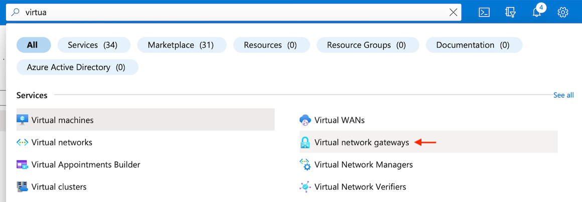
First, search for Virtual network gateways in your Azure portal:
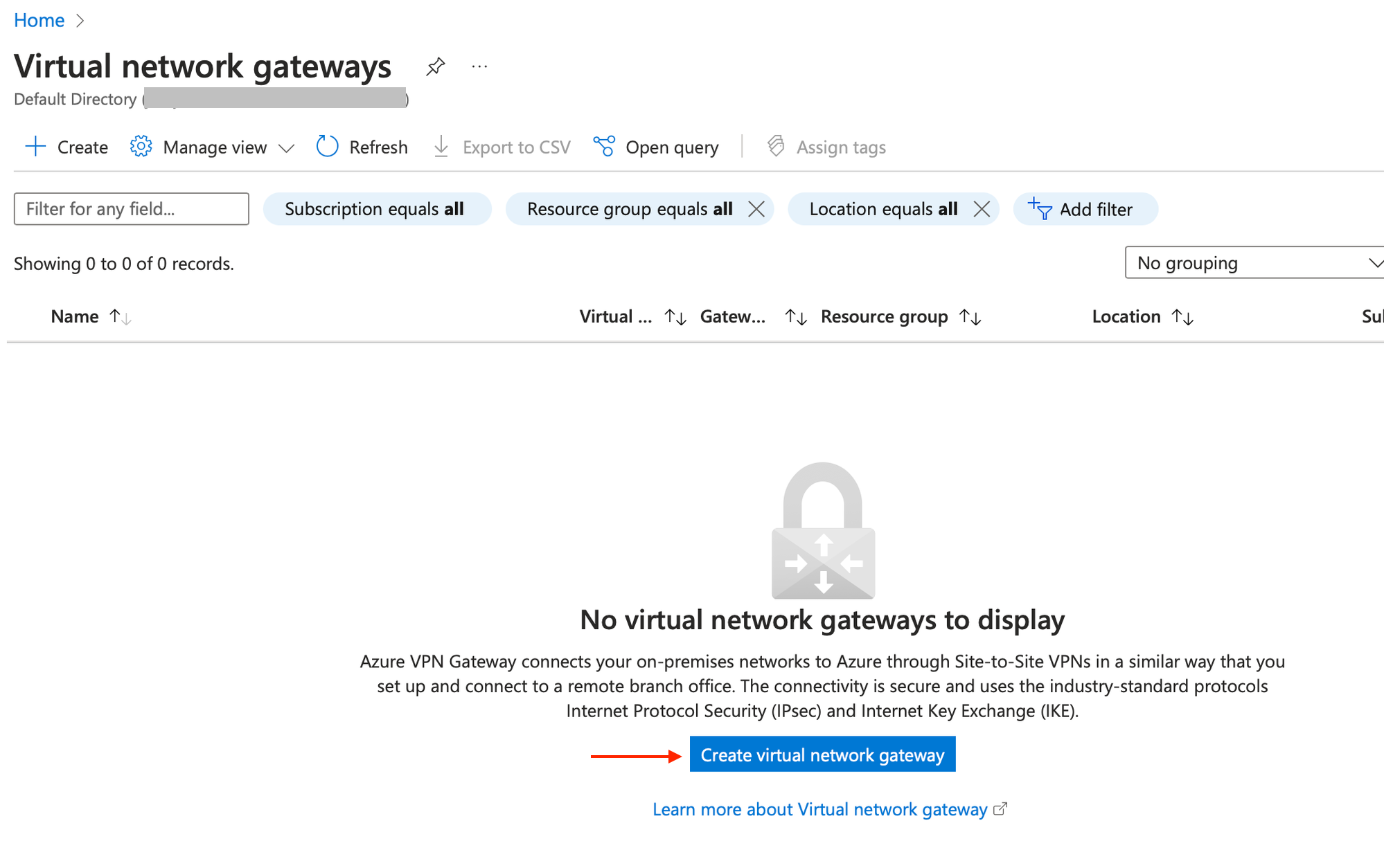
Once the page opens, click on Create virtual network gateway:
Here are the information we will set for the Virtual network gateway (VNG):
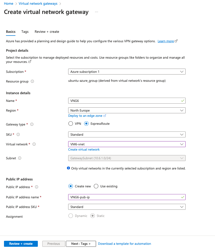
- Name: set a name
- Region: North Europe
- Gateway type: ExpressRoute
- SKU: Standard
- Virtual network: Select your Vnet
- Subnet: The GatewaySubnet (10.6.1.0/24) is automatically selected
- In the Public IP seetings: Select create new, give it a name and select a standard SKU
Go to the Review + create and click on Create:
It can take a while to be setup (between 5-25 min). Once it is done, the page displays Your deployment is complete:
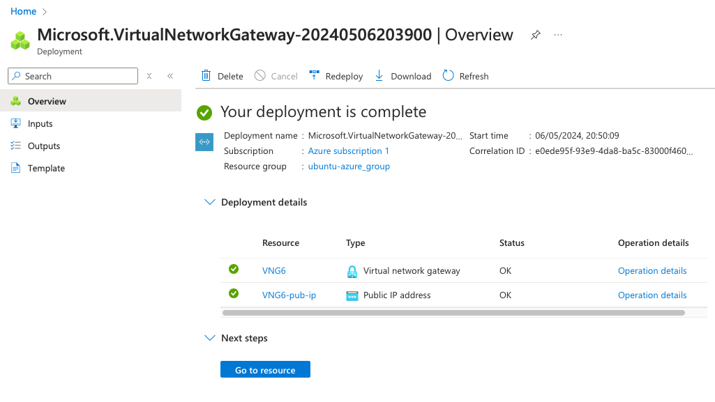
So far we have created a VNet and a Virtual network gateway (VNG). Now we will setup the last part in Azure, which is linking the Virtual network gateway (VNG) to the ExpressRoute circuit.
Gateway connection
The Gateway connection will be configured to enable the use of the ExpressRoute circuit by resources inside the Virtual Network.
To configure it, go onto the Virtual network gateway page that we’ve just deployed. On the left, under Settings click on Connections > Add:
Then click on the Add button to start configuring the Gateway connection:
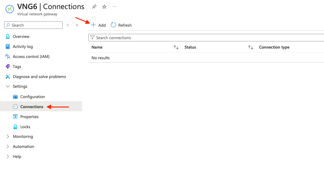
On the Create connection page, under the Basics tab:
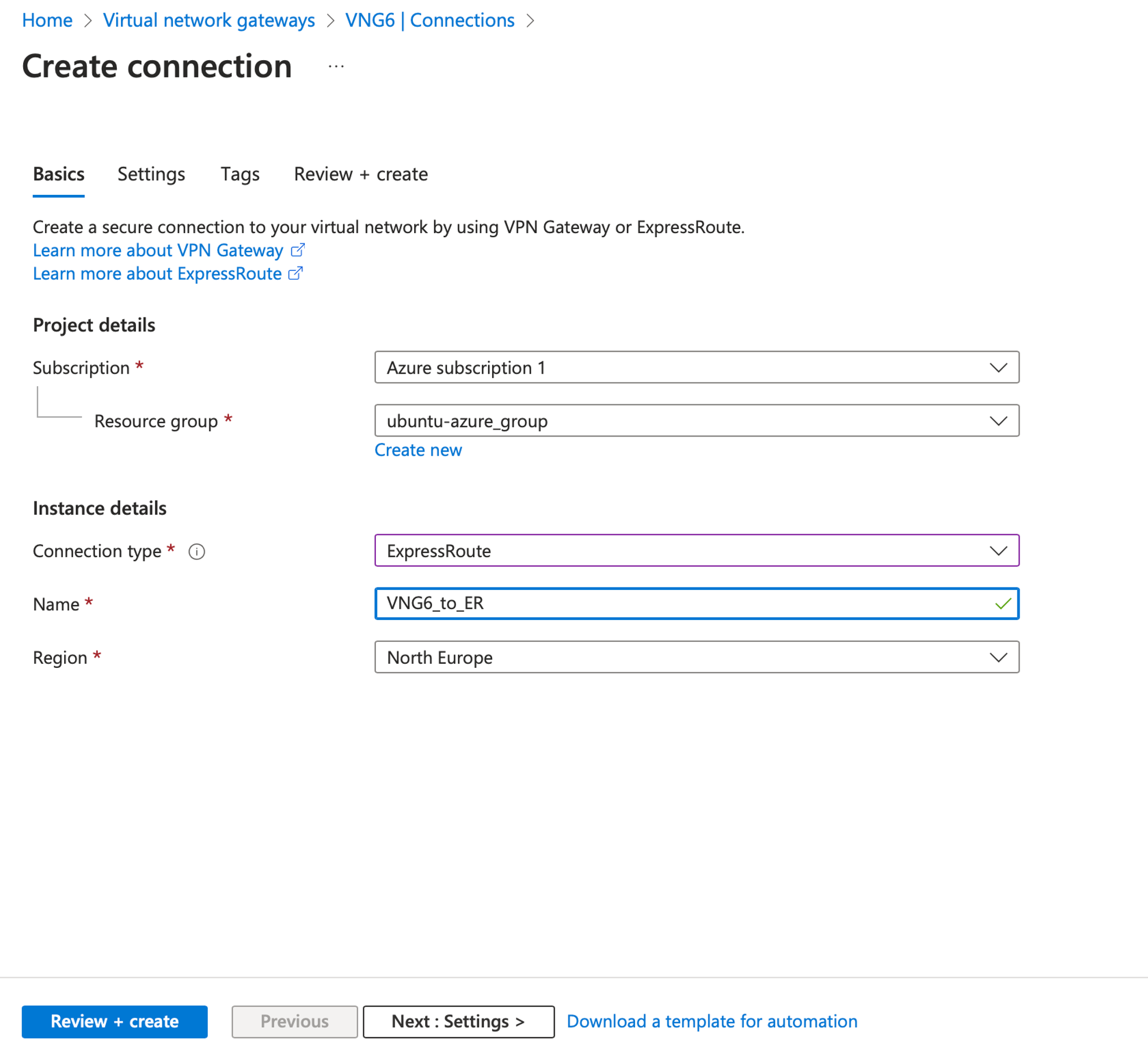
- Connection type: ExpressRoute
- Name: set a name for the Gateway connection
- Region: Although the Gateway connection is region free, we set the location similar to the Virtual network gateway (VNG) to save money
On the Settings tab:
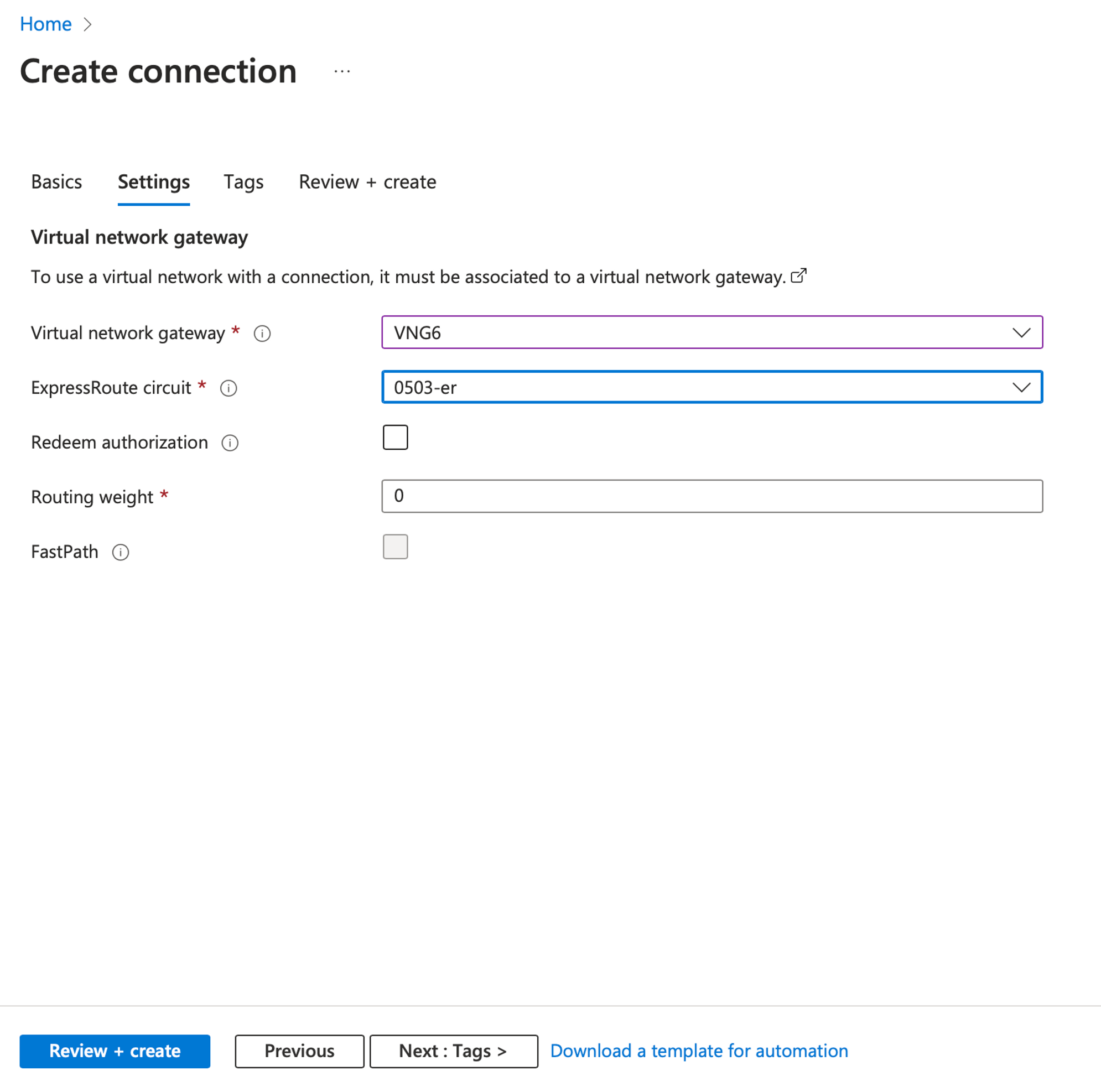
- Virtual network gateway: select the one previously made
- ExpressRoute circuit: select the ER circuit
- Routing weight: 0
Then click on Review + create and Create.
Once created, a Gateway connection page with all information can be seen:
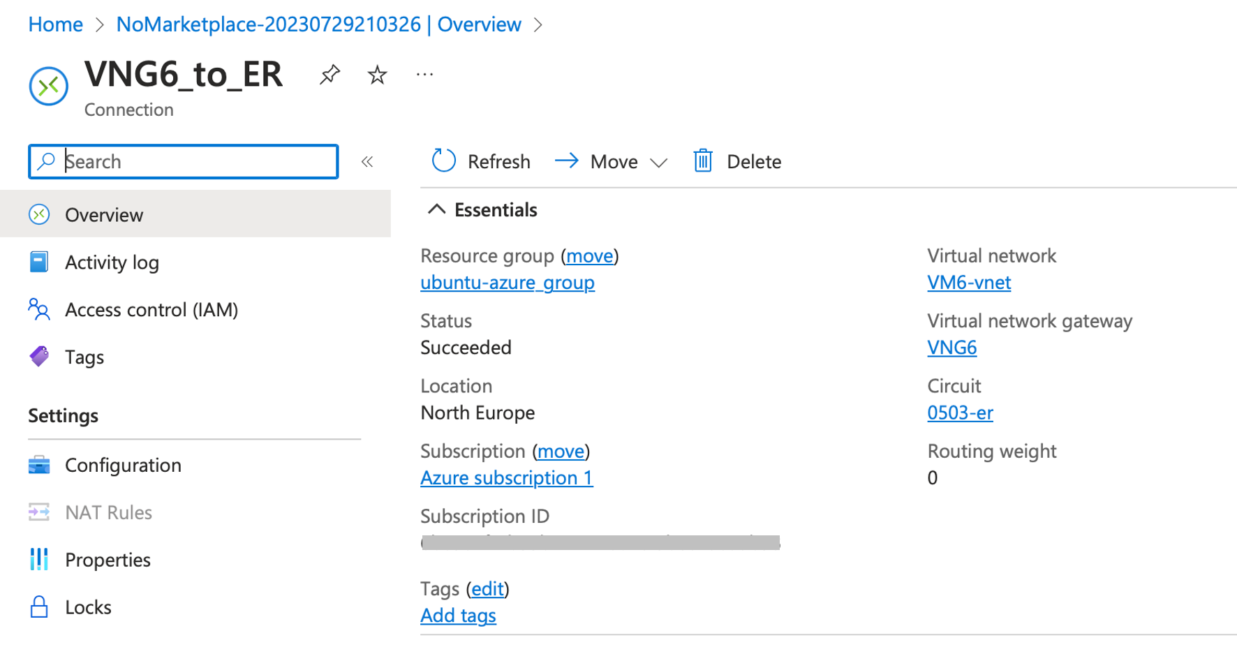
The Azure infrastructure setup is complete. Next, we’ll examine AWS, Azure and Cloud Router table to ensure every prefixes are advertised and received. Then, we’ll conduct connectivity tests with VMs located in both CSP. Since this tutorial focuses on demonstrating a MultiCloud infrastructure, VM creation is not covered. Ensure to create the VMs within the VPC subnet for AWS and inside the VNet for Azure. Additionally, customize both security groups to permit ICMP if you intend to use ping.
PART IV - Verification and measurements
Route table verification
AWS BGP route table
On AWS, because we enabled route propagation, we should have received BGP Updates corresponding to the Azure prefixes (10.6.0.0/16). To verify that, go to the route table page details, then to the Routes tab:
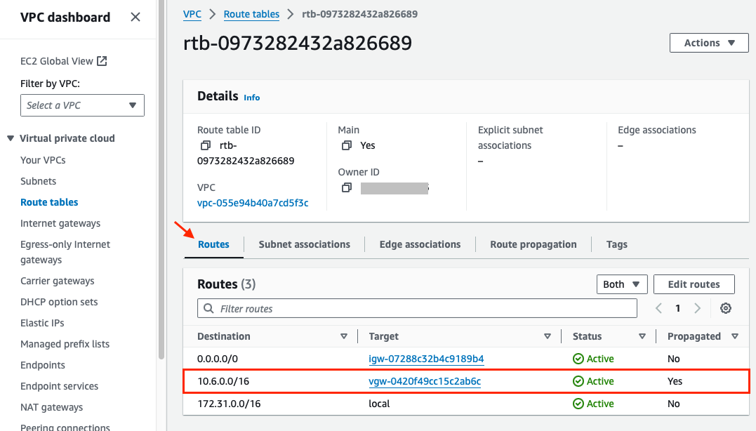
AWS virtual machines and other resources that are part of this VPC (and its routing table) can now reach Azure VNet subnet (10.6.0.0/16) through the Virtual private gateway.
Azure BGP route table
Now let’s have a look if we are receiving BGP prefixes from AWS.
Go to the ExpressRoute circuits page > select your circuit (0503-er in my case) > under Peerings, click on the “…” dots at the right of the Azure private line, and select View route table:

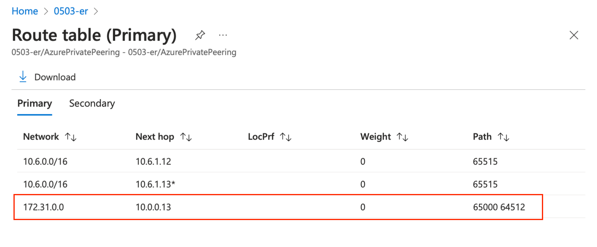
We can see the Azure VNet subnet (10.6.0.0/16) and the AWS VPC subnet (172.31.0.0) that can be reached via Cloud Router as Next Hop (10.0.0.13).
Cloud Router VRF route table
Connect to your Cloud Router instance (using ssh or via the Next Packet portal) and run the show route command:
jvetter@nxp-fra-01:l2> show route

d87ed303-8b9d-48a5-9f08-aa42b4b50cd8.inet.0: 7 destinations, 7 routes (7 active, 0 holddown, 0 hidden
+ = Active Route, - = Last Active, * = Both

10.0.0.0/31       *[Direct/0] 22:35:52
                    > via irb.4
10.0.0.0/32       *[Local/0] 22:35:52
                      Local via irb.4
10.0.0.12/30      *[Direct/0] 22:35:52
                    > via irb.2
10.0.0.13/32      *[Local/0] 22:35:52
                      Local via irb.2
10.6.0.0/16       *[BGP/170] 22:35:46, localpref 100
                     AS path: 12076 I, validation-state: unverified
                    > to 10.0.0.14 via irb.2
172.31.0.0/16     *[BGP/170] 00:13:39, localpref 100
                     AS path: 64512 I, validation-state: unverified
                    > to 10.0.0.1 via irb.4
Connectivity test
ICMP
Brief ICMP echo send via ping, default MTU. From Azure VM to AWS VM.
azure-vm$ ping 172.31.30.100
PING 172.31.30.100 (172.31.30.100) 56(84) bytes of data.
64 bytes from 172.31.30.100: icmp_seq=1 ttl=62 time=38.4 ms
64 bytes from 172.31.30.100: icmp_seq=2 ttl=62 time=37.9 ms
^C
--- 10.6.0.4 ping statistics ---
2 packets transmitted, 2 received, 0% packet loss, time 1001ms
rtt min/avg/max/mdev = 37.941/38.178/38.415/0.237 ms
Jumbo frame
Azure and VM MTU: The default MTU for Azure VMs is 1,500 bytes. The Azure Virtual Network stack will attempt to fragment a packet at 1,400 bytes. Note that the Virtual Network stack isn’t inherently inefficient because it fragments packets at 1,400 bytes even though VMs have an MTU of 1,500. A large percentage of network packets are much smaller than 1,400 or 1,500 bytes.
According to Microsoft “Increasing MTU isn’t known to improve performance and could have a negative effect on application performance. Hybrid networking services, such as VPN, ExpressRoute, and vWAN, support a maximum MTU of 1400 bytes.” source : https://learn.microsoft.com/en-us/azure/virtual-network/virtual-network-tcpip-performance-tuning
Performance test
UDP test with bandwidth at 50Mbps and 30Mbps, default IP MTU (1500 bytes). Azure VM as listener. AWS VM as sender.
azure-vm$ iperf -s
------------------------------------------------------------
Server listening on TCP port 5001
TCP window size:  128 KByte (default)
------------------------------------------------------------
[  4] local 10.6.0.4 port 5001 connected with 172.31.30.100 port 34562
[ ID] Interval       Transfer     Bandwidth
[  4]  0.0-10.2 sec  41.9 MBytes  34.4 Mbits/sec


aws-vm$ iperf -c 10.6.0.4 -u -b 50M -i 1 -t 10
------------------------------------------------------------
Client connecting to 10.6.0.4, UDP port 5001
Sending 1470 byte datagrams, IPG target: 224.30 us (kalman adjust)
UDP buffer size:  208 KByte (default)
------------------------------------------------------------
[  3] local 172.31.30.100 port 51830 connected with 10.6.0.4 port 5001
[ ID] Interval       Transfer     Bandwidth
[  3]  0.0- 1.0 sec  6.25 MBytes  52.4 Mbits/sec
[  3]  1.0- 2.0 sec  6.25 MBytes  52.4 Mbits/sec
[  3]  2.0- 3.0 sec  6.25 MBytes  52.4 Mbits/sec
[  3]  3.0- 4.0 sec  6.25 MBytes  52.4 Mbits/sec
[  3]  4.0- 5.0 sec  6.25 MBytes  52.4 Mbits/sec
[  3]  5.0- 6.0 sec  6.25 MBytes  52.4 Mbits/sec
[  3]  6.0- 7.0 sec  6.25 MBytes  52.4 Mbits/sec
[  3]  7.0- 8.0 sec  6.25 MBytes  52.4 Mbits/sec
[  3]  8.0- 9.0 sec  6.25 MBytes  52.4 Mbits/sec
[  3]  0.0-10.0 sec  62.5 MBytes  52.4 Mbits/sec
[  3] Sent 44583 datagrams
[  3] Server Report:
[  3]  0.0-10.2 sec  43.3 MBytes  35.4 Mbits/sec  15.586 ms 13724/44584 (31%)


aws-vm$ iperf -c 10.6.0.4 -u -b 30M -i 1 -t 10
------------------------------------------------------------
Client connecting to 10.6.0.4, UDP port 5001
Sending 1470 byte datagrams, IPG target: 373.84 us (kalman adjust)
UDP buffer size:  208 KByte (default)
------------------------------------------------------------
[  3] local 172.31.30.100 port 35093 connected with 10.6.0.4 port 5001
[ ID] Interval       Transfer     Bandwidth
[  3]  0.0- 1.0 sec  3.75 MBytes  31.5 Mbits/sec
[  3]  1.0- 2.0 sec  3.75 MBytes  31.5 Mbits/sec
[  3]  2.0- 3.0 sec  3.75 MBytes  31.5 Mbits/sec
[  3]  3.0- 4.0 sec  3.75 MBytes  31.5 Mbits/sec
[  3]  4.0- 5.0 sec  3.75 MBytes  31.5 Mbits/sec
[  3]  5.0- 6.0 sec  3.75 MBytes  31.5 Mbits/sec
[  3]  6.0- 7.0 sec  3.75 MBytes  31.5 Mbits/sec
[  3]  7.0- 8.0 sec  3.75 MBytes  31.5 Mbits/sec
[  3]  8.0- 9.0 sec  3.75 MBytes  31.5 Mbits/sec
[  3]  0.0-10.0 sec  37.5 MBytes  31.5 Mbits/sec
[  3] Sent 26750 datagrams
[  3] Server Report:
[  3]  0.0-10.0 sec  37.4 MBytes  31.4 Mbits/sec   0.174 ms   84/26750 (0.31%)
[  3] 0.0000-9.9977 sec  1 datagrams received out-of-order
By trying to use the full circuit bandwidth (50Mbps) we can observe more than 30% packet loss. It goes down to 0.31% packet loss after reducing the bandwidth. I havent had the time to perform a test with a lower MTU, but I suspect this is due to the fragmentation as Microsoft warned about ExpressRoute circuit.
Conclusion
This article presented the advantages of multicloud architectures, outlined the process of interconnecting multiple CSP, and the benefits of leveraging third-party solutions like Cloud Router for this purpose.
In summary, platforms such as Cloud Router facilitate multicloud connectivity, offering seamless connectivity and ensuring private and flexible communication.
Special thanks to the Next Packet team for providing access to the Cloud Router Beta version. Your feedback is greatly valued; please don’t hesitate to reach out with any comments or questions at hello [AT] jvetter [DOT] net. Thank you for reading!
-
Next Packet also offer the possibility to have bare metal box (Juniper, Cisco or Nokia, where you have a slice of the ASIC directly, you chose the number of ports you want and you have a dedicated part of the FIB. The isolation provided prevent to see resources from other tenant).* ↩︎
-
SKU (Stock Keeping Unit): In various contexts such as VMs, storage, or ExpressRoute Circuits, SKU specifies the characteristics like performance metrics, pricing details, and limitations. Specifically for ExpressRoute circuits, SKU determines factors like the number of learned routes, maximum circuit limits, and additional capabilities such as FastPath. If standard, you would normally be able to route locally inside Azure Germany. If you want to route outside in another region also, you have to chose premium (and as premium suppose, the price will be different). For our setup, standart is enough. ↩︎
In this series:
- Multicloud infrastructure with AWS, Azure and Cloud Router